Delivery system for medical devices

Active Publication Date: 2005-04-28
ABBOTT CARDIOVASCULAR
View PDF44 Cites 287 Cited by
  • Summary
  • Abstract
  • Description
  • Claims
  • Application Information

AI Technical Summary

Benefits of technology

[0014] The present invention is directed to a delivery system for delivering and more accurately deploying a medical device, such as a stent, to the target site in a body lumen. The delivery system in accordance with the present invention incorporates unique features which facilitates minimal movement during device deployment, accurate placement, and single-handed system operation. The delivery system of the present invention can be manufactured in an Rx design or platform to improve the speed in delivering the cat

Problems solved by technology

One of the difficulties encountered in using prior art stents involve maintaining the radial rigidity needed to hold open a body lumen while at the same time maintaining the longitudinal flexibility of the stent to facilitate its delivery and accommodate the often tortuous path of the body lumen.
However, problems have been associated with such prior art delivery systems.
For example, systems which rely on a “push-pull design” or “pull-back design” can experience unwanted movement of the collapsed stent within the body vessel when the inner member is pushed forward which can lead to inaccurate stent positioning.
This change of the geometry of the system within the anatomy can lead to inaccurate stent positioning.
Failure to do so may result in deploying the stent beyond the target area and can cause the stent to bunch up.
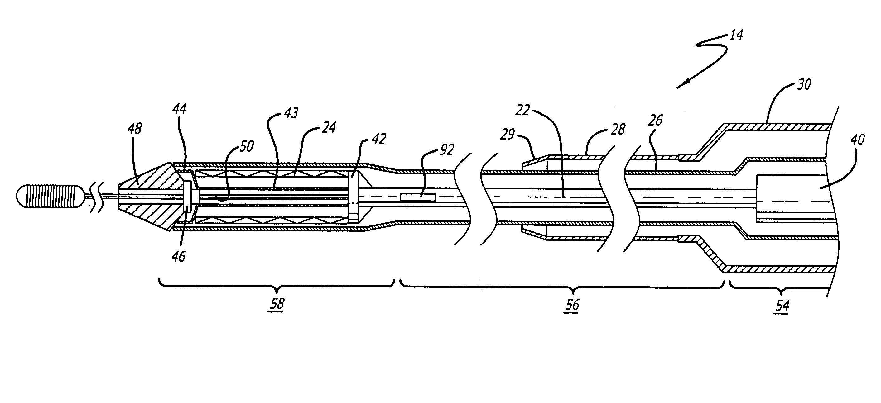
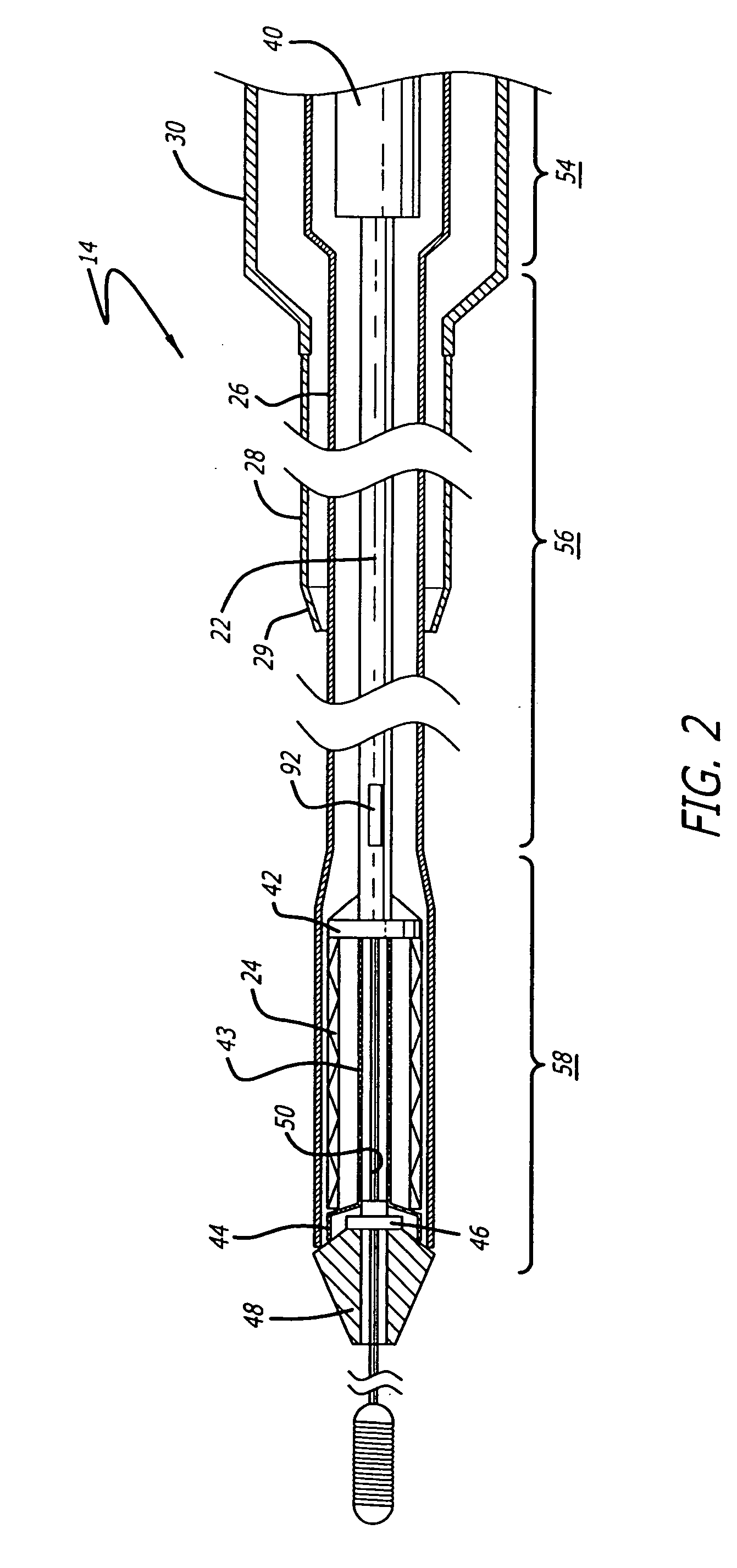
When the outer sheath is retracted proximally into the deployment handle during deployment, the length of the exposed outer sheath tends to shorten.
However, the outer sheath tends to shorten during deployment, thus changing the shape of the exposed portion of the catheter.
As a result, the movement of the inner catheter member caused by the retraction of the outer sheath can cause the stent to deploy prematurely and at a location beyond the targeted site.
As a result, less than accurate deployment of the stent can occur.
However, if the delivery system is not kept straight during deploym

Method used


Image

  • Delivery system for medical devices
  • Delivery system for medical devices
  • Delivery system for medical devices

Examples


Embodiment Construction

[0040] The present invention relates to a delivery system for delivering and deploying a medical device into a target site in a patient's body, such as a body lumen. For sake of illustration, the following exemplary embodiments are directed to a delivery system for delivering and deploying a self-expanding stent, although it is understood that the present invention is applicable to other medical devices which are implantable in a body lumen as well as other parts of the body. Additionally, the medical device can be either a self-expanding device or a non self-expanding device.

[0041] Referring now to FIGS. 1 and 2, in one particular embodiment of the present invention, the delivery system 10 incorporating features of the present invention includes a control handle 12 and a catheter portion 14. As can best be seen in FIG. 1, the control handle includes a hand portion 16 which allows the physician to hold the control handle utilizing one hand. The control handle 12 also includes a rot...


PUM


Abstract

The invention is directed to a delivery system for implantation a self-expanding medical device in a body which includes a control handle and a catheter portion. The catheter portion includes an outer restraining member which covers the collapsed, medical device, an inner catheter member having a distal end including a region upon which the medical device is mounted, and an outer sheath which is removably attached to the control handle. The outer sheath creates a conduit for the catheter portion to prevent the inner catheter member from moving axially when the outer restraining member is retracted. The control handle has a rotatable thumbwheel to actuate a retraction mechanism attached to the proximal end of the outer restraining member which moves the restraining member in a proximal direction to deploy the medical device.

Description

CROSS-REFERENCE TO RELATED APPLICATION [0001] This application is a continuation-in-part of Ser. No. 10 / 661,406 filed Sep. 12, 2003, which is assigned to the same Assignee as the present application, the contents of which are hereby incorporated by reference.BACKGROUND OF THE INVENTION [0002] The present invention relates generally to delivery systems for delivering and deploying medical devices, such as stents, which are adapted to be implanted into a patient's body, such as a blood vessel and, more particularly, to a delivery system for more accurately deploying a self-expanding medical device into an area of treatment. [0003] Stents are generally cylindrically shaped devices which function to hold open and sometimes expand a segment of a blood vessel or other arterial lumen, such as coronary artery. Stents are usually delivered in a compressed condition to the target site and then deployed at that location into an expanded condition to support the vessel and help maintain it in a...

Claims


Application Information

Patent Timeline
IPC IPC(8): A61F2/06A61F2/84
CPCA61F2/95A61F2/966A61F2002/9517A61M25/0021A61M2025/0681A61M2025/006A61M2025/0062A61M2025/0098A61M2025/0183A61M25/0023A61F2/9517
Inventor WU, PATRICK P.FITZGERALD, KEIFKLOCKE, STEPHANIE
Owner ABBOTT CARDIOVASCULAR
Why Eureka
Try Eureka