
Tilt mechanism for a chair

a tilting mechanism and chair technology, applied in the direction of chairs, movable seats, transportation and packaging, etc., can solve the problems of difficult to achieve the pivot point during tilting activities, chair design, etc., and achieve the effect of reducing “shirt shear, good stability in the chair, and minimal movement of users

Inactive Publication Date: 2009-06-18
L & P PROPERTY MANAGEMENT CO
View PDF6 Cites 19 Cited by
  • Summary
  • Abstract
  • Description
  • Claims
  • Application Information

AI Technical Summary

Benefits of technology

[0007]Such proportional and asynchronous movement schemes provide many benefits to the chair occupant moving between an upright position and a reclined position. Examples of these benefits include proper support for the user's back, reduced “shirt shear”, or the upward and downward pull on a user's shirt by the chair back, minimal movement of the user's center of gravity relative to the pedestal or other substructure of the chair (to maintain good stability in the chair), minimal change to the user's sight or reach distance from a working surface (e.g., a computer display screen), among other benefits. The tilt mechanism, in embodiments, also facilitates the chair (and seat) being generally self-weighting, such that a traditional tensioning mechanism affecting chair backward tilting is essentially unnecessary.

Problems solved by technology

Still, even with the benefits provided by known combined movement chairs, a chair design that minimizes user strain and works in coordination with the pivoting of a person's body about their natural hip pivot point during tilting activities has proven elusive.

Method used


Image

  • Tilt mechanism for a chair
  • Tilt mechanism for a chair
  • Tilt mechanism for a chair

Examples


Embodiment Construction

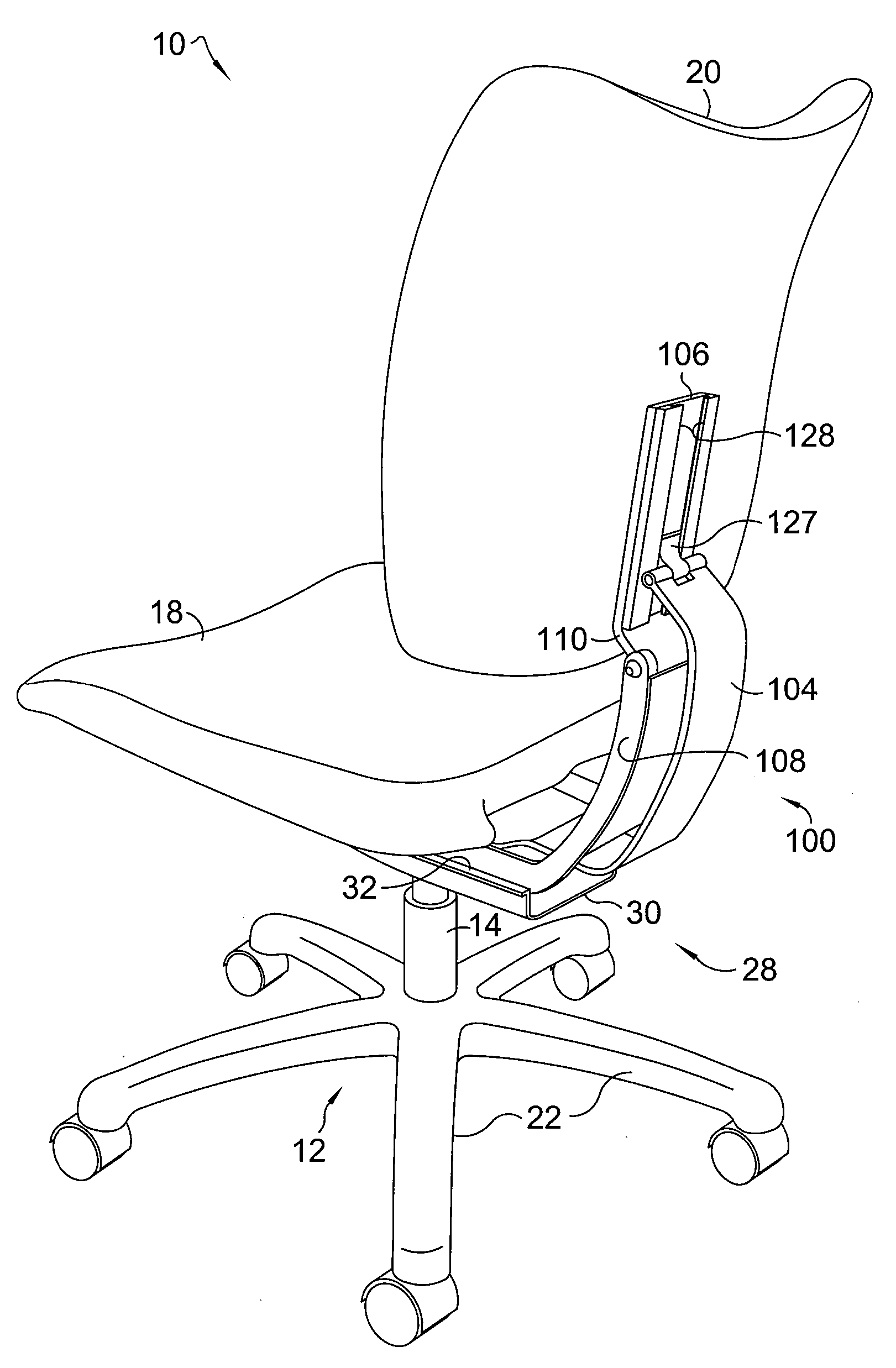
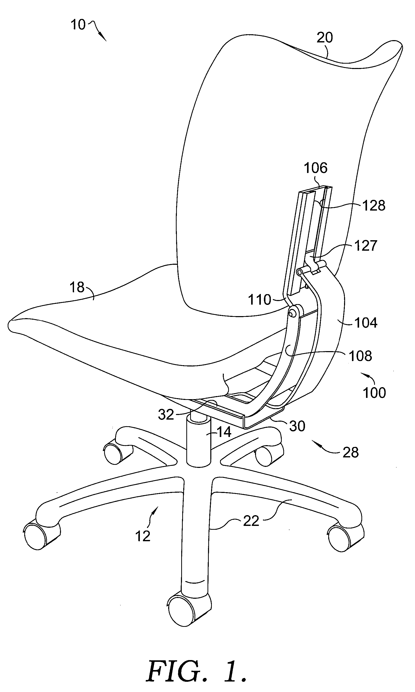
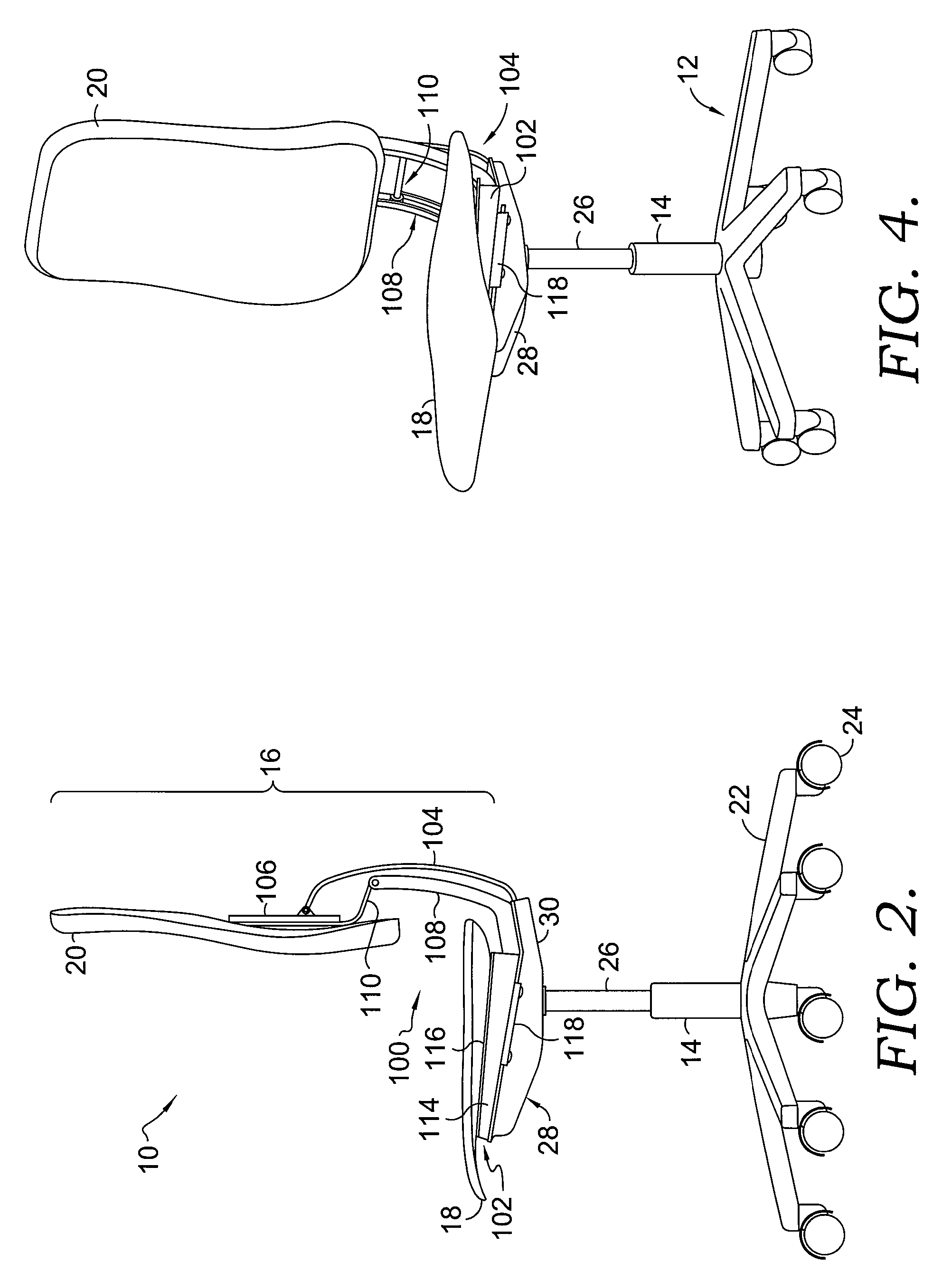
[0021]Referring to the drawings in greater detail and initially to FIGS. 1 and 2, an exemplary chair employing a tilt mechanism of the present invention is designated generally by the numeral 10. As is known in the art, a conventional office-type chair has a base assembly 12 with a pedestal column 14 extending upwardly therefrom to support a superstructure 16 of the chair 10. The chair superstructure 16 includes, among other things, a chair seat 18, a chair back 20, and components to interconnect the seat 18 with the back 20 (i.e., a tilt mechanism). The base assembly 12 includes a number of support legs 22 extending radially from the column 14 and a corresponding number of castors 24 operably supported on the outer ends of the support legs 22. Additionally, a gas cylinder 26 or other lifting mechanism is preferably supported by the column 14 to enable the height of the seat 18 (and thus the chair superstructure 16) to be adjusted by an occupant.

[0022]It should be understood that va...


PUM


Abstract

A tilt mechanism provides improved coordination in the motions of a chair seat and a chair back during chair tilt. In one aspect, the tilt mechanism includes a seat base, a back bracket, a back support bar, a guide track and a back follower member. The seat base is slidably coupled to the chassis and rigidly coupled to the chair seat. The back support bar is configured for moveable engagement with the back bracket coupled with the chair back. Additionally, the back follower member, coupled with the chair back, is received within one or more channels formed in the guide track for moveable engagement therewith. A proportional and asynchronous action is achieved via the back bracket moving relative to and in engagement with the back support bar, the back follower member moving within the guide track and the seat base sliding forwardly relative to the chassis.

Description

BACKGROUND OF THE INVENTION[0001]Office-type chairs are commonly utilized in modern working environments to provide an occupant with a level of comfort while performing certain tasks that require a person to be in a seated position for an extended length of time. One common configuration for such a chair includes a mobile base assembly (to allow the chair to roll across a floor) and a pedestal column supporting the superstructure of the chair. A chassis is also provided to enable the user to adjust certain settings of the chair and to facilitate recline or “tilt” of the chair superstructure, including the seat and back of the chair. This basic chair configuration allows the user to change their sitting position in the chair as desired, such that fatigue is minimized during long sitting periods.[0002]In recent years, chair designs have implemented a feature where a chair back and seat both move simultaneously during a tilting or rearwardly reclining motion, with the back generally ti...

Claims


Application Information

Patent Timeline
Patent Type & Authority Applications(United States)
IPC IPC(8): A47C1/024
CPCA47C1/03294A47C1/03255
Inventor JOHNSON, LEROY B.CROSSMAN, PHILIP
Owner L & P PROPERTY MANAGEMENT CO
Learn More