[0008] An object of the present invention is to provide a high strength substructure for
prosthodontics, such as crowns and bridges. Another object of the present invention is to provide a process for manufacturing
prosthodontics having a high strength substructure. Yet another object of the instant invention is to provide a substructure reinforcement for prosthodontic substructures. Still another object of the instant invention is to provide a process for manufacturing
prosthodontics having a reinforced substructure. Another object of the instant invention is to provide a strengthening mechanism for prosthodontic substructures close to the region where the stress is being applied to the structure. Another object of the instant invention is to provide a prosthodontic substructure that is aesthetically pleasing and which is relatively simple to design and construct.
[0010] In a preferred embodiment, the reinforcement structure of the instant invention is incorporated into the CAD-
CAM design stage for a high-strength, milled substructure. The design of this reinforcement structure depends on the
software associated with each CAD-
CAM system. The reinforcement structure may be designed primarily manually using conventional CAD-
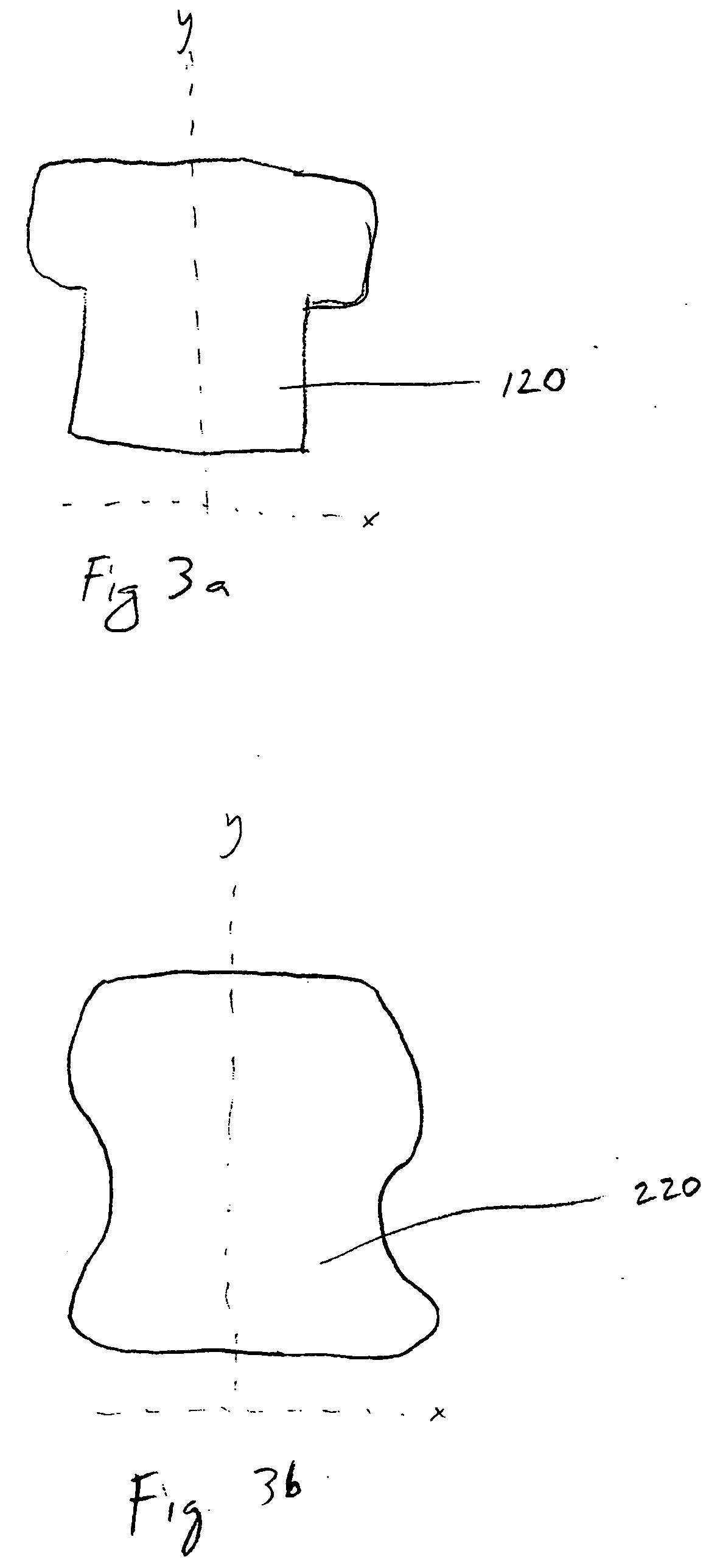
CAM design software, which allows a user to place pre-made shapes down over an image on the screen, increase or decrease the existing shape, distort the shape in one / multiple vanishing points, increase the volume of the shape from a point-angle or free hand-paint an area. In one preferred embodiment, the reinforcement structure of the instant invention is designed primarily automatically by a CAD-CAM (or other
software) application that includes a pull down annular shape that is placed around the concentric image being made over the die from a
library of tools in the
software palate. The annular shape may be enlarged (or reduced) in x, y, and z axis as necessary to bulk-up (or down) the core being designed. In another preferred embodiment, the reinforcement structure of the instant invention is designed primarily automatically by a CAD-CAM (or other software) application by the operator pulling the structure from a point, line, cluster of points, etc., to distort a portion of the shape of the main body of the substructure to create the reinforcement structure without distorting the overall shape of the main body. In yet another preferred embodiment, the reinforcement structure of the instant invention is pre-designed into the main body of the substructure. In such an embodiment, a basic shape for the main body of the substructure is selected from a
library of shapes available in the software application based upon the desired shape for the final restoration, with the reinforcement structure already built into the shape of the main body. The operator then either pushes, pulls, takes away or otherwise erases portions of the pre-designed shape of the main body (including the reinforcement structure) to meet the needs for the specific restoration. In still another preferred embodiment, the substructure (including the reinforcement structure of the instant invention) is designed by first obtaining the desired shape for the restoration and then subtracting away or deconstructing from that shape to leave the substructure shape. In such an embodiment, the part of the final shape that is subtracted is determined to maximize the aesthetic appearance of the final restoration by concealing the substructure.
[0011] In one embodiment the reinforcement structure is over-built in the CAD-CAM
design phase on a relatively freehand basis (or through use of the automatic software discussed above), preferably at the crest of the preparation, and protruding about 2 mm out from the base coping. After milling is completed, the contact regions are adjusted, and the amount of the lingual and labial prominence is modified as desired, by hand. If necessary or desired, the reinforcement structure is thinned out after milling. There is little requirement for bulk of the reinforcement structure because the high-strength non-metal substructure of the instant invention is not only strong, it is also very rigid. The final frame design is easy to design, construct and manage.
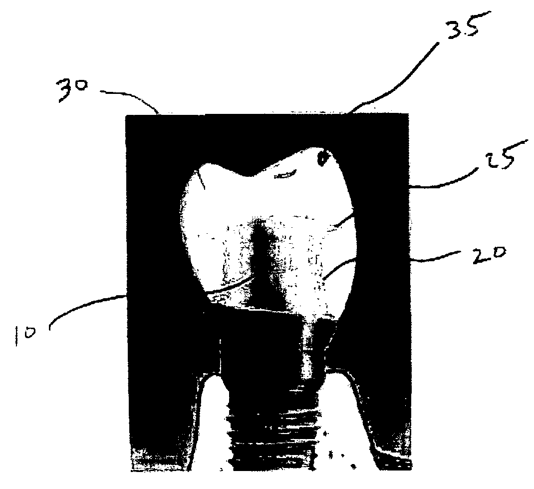
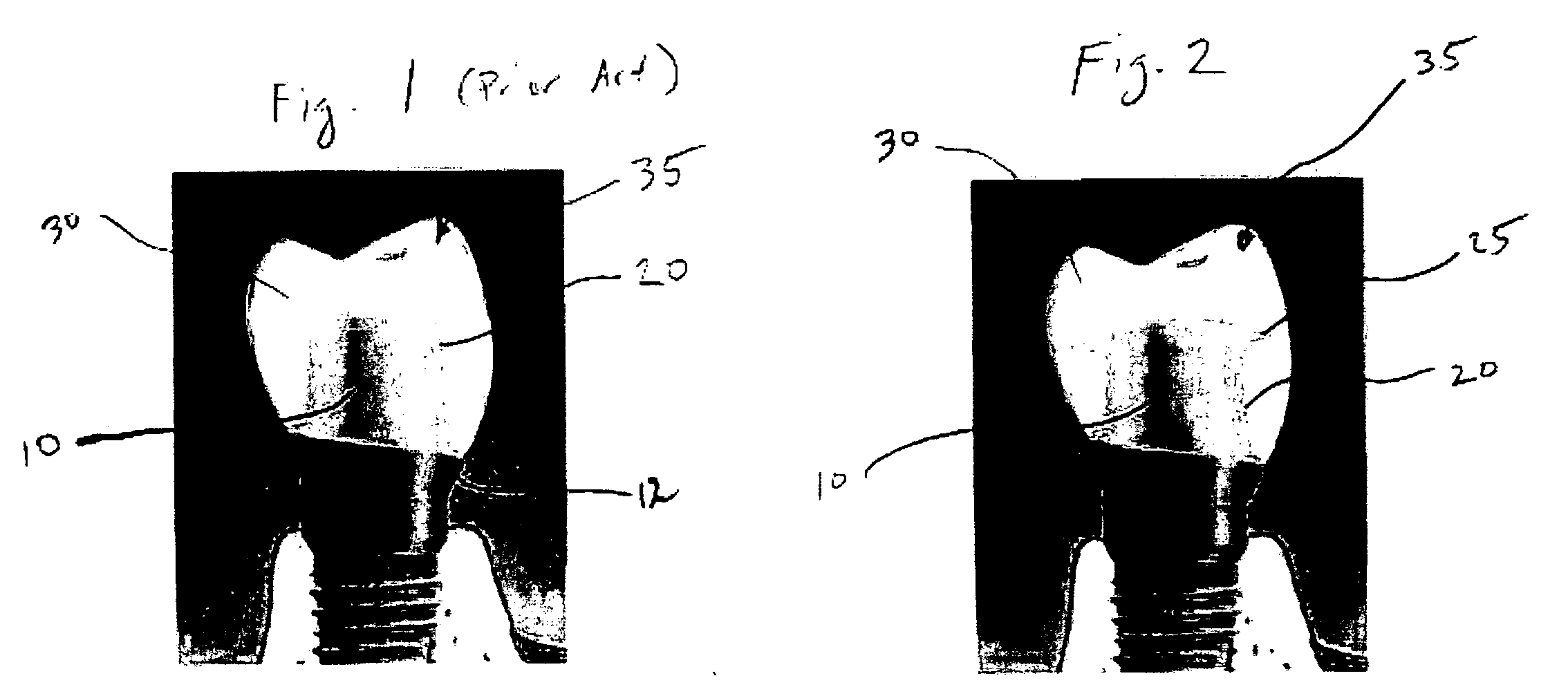
[0012] The aesthetic appearance of the piece is increased by reducing the potential for the sub-structure to “Shine-Through” the surface of the final restoration at the mesio-buccal region. To minimize Shine-Through, the prominent sub-structure may be reduced through the crown contour. Veneering porcelain is then applied over the deficiency. In addition, the reinforcement structure may be masked when the final restorations are characterized.
[0013] The reinforcement structure of the instant invention has the
advantage that the marginal display of opaque porcelain from the underlying high strength core can be minimized, because there is no need for a heavy bulky collar to
gain strength or to provide support. The
normal thickness of the base coping can be extended to the margin. This is particularly useful in
implant based units, where there tends to be a bigger build out from a relatively narrow base.
[0015] The reinforcement support of the instant invention is remarkably simple to incorporate and use in practice. In one embodiment of the instant invention, for single unit restorations, a
thin layer coping is designed over the preparation (such as a pre-manufactured
implant abutment, a custom manufactured
implant abutment, prepared portion of tooth on which restorations is supported, etc.) with a relatively crude shaping of the reinforcement structure. In the preferred embodiment, the inventive reinforcement structure is established at the height of the contact point and parallels the
occlusal plane. When the reinforcement structure has been established relatively crudely in the
design stage, it can then be refined quickly once the unit is positioned on a master model.

