
Expandable intervertebral spacer

a technology of intervertebral spacers and expandable implants, which is applied in the field of expandable implants, can solve the problems of relative complexity of the delivery procedure, large entry hole in the body required to insert the device, and severe pain

Active Publication Date: 2005-06-30
KYPHON
View PDF106 Cites 510 Cited by
  • Summary
  • Abstract
  • Description
  • Claims
  • Application Information

AI Technical Summary

Benefits of technology

[0010] In a preferred embodiment of the invention, the radial expansion of the spacer is utilized to achieve a high intra-vertebral fill, without an overly invasive surgical procedure. Preferably, a high contact surface between the spacer and the vertebrae is achieved.
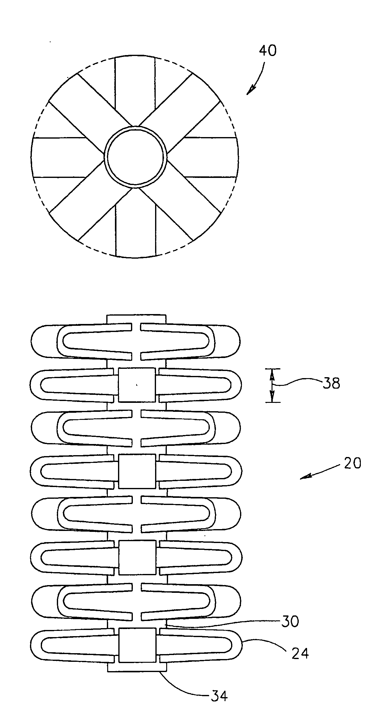
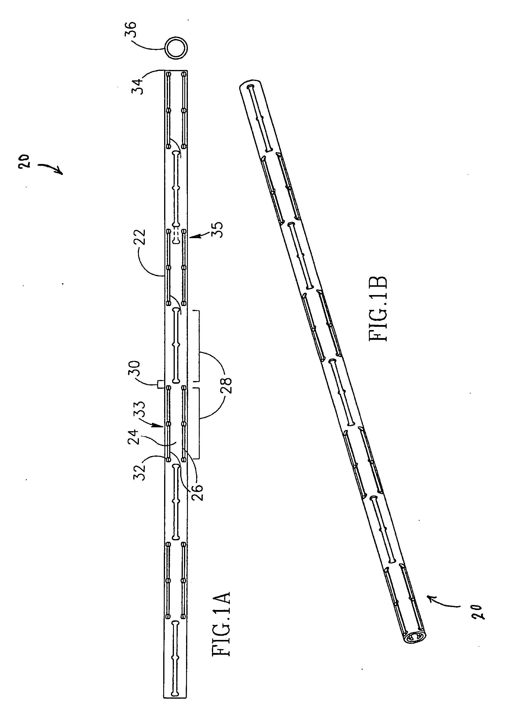
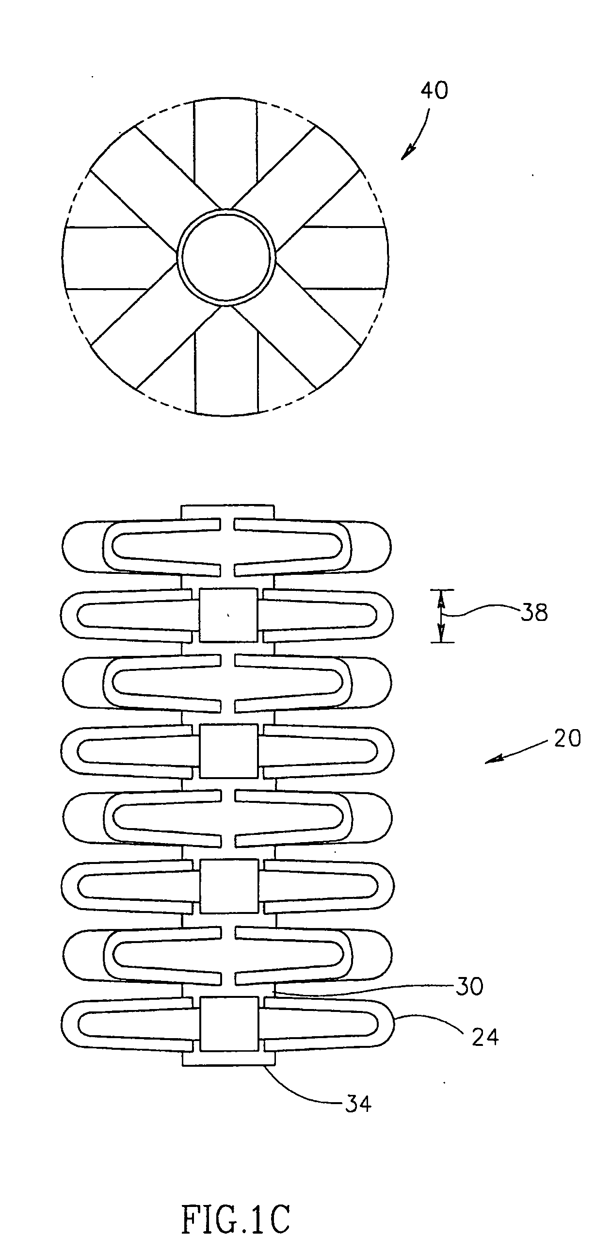
[0014] A finished spacer, in accordance with some preferred embodiments of the invention, comprises a plurality of spikes that are provided into the body to provide a desired geometrical shape, for example to space apart two vertebrae. The tube body parts that do not expand, serve to interconnect the spikes, for example to prevent them from getting lost and / or for aiding in or performing guiding the final placement of the spikes, so that the desired final geometry is achieved. Thus, geometric constructs other than spikes may also be provided to a same effect.
[0023] An aspect of some preferred embodiments of the invention relates to forming the tube of a material having an uneven thickness and / or mechanical properties. In some embodiments, mechanical characteristics of a spacer are modified after the spacer (or a tube from which it is cut) is constructed. In other embodiments, such mechanical characteristics may be at least partly modified before the spacer is formed. In a preferred embodiment of the invention, increased thickness and / or strength is provided at points or areas where stress is concentrated when pressure is applied to the spikes in an expanded spacer. Alternatively or additionally, increased thickness and / or strength is provided at points where stress is concentrated when pressure is applied to the spikes in an expanded spacer. Alternatively or additionally, increased thickness and / or one or more protrusions are provided on one or more spikes to mechanically block a collapsing of the spikes after the tube is expanded. In one example, when the spacer comprises alternating segments of spikes, a segment may include one or more protrusions which strengthen the spikes on an adjacent segment. Alternatively or additionally, a lower strength and / or pre-stressing is applied to portions of the tube which are expected to fold (and / or stretch) when the tube is expanded. Alternatively or additionally, variations in thickness and / or strength and / or elasticity define portions of the spacer which better conform to surrounding tissue. In some embodiments of the invention, the spacer matches the geometry of the surrounding tissue. In other embodiments, the mechanical characteristics of the spacer are matched to the surrounding tissue, for example providing more give where the spacer is against a hard bone.
[0024] An aspect of some preferred embodiments of the invention relates to a inter-vertebral spacer having extending spikes, in which at least some of the spikes have a non-V shaped profile. In a preferred embodiment of the invention, the spikes have a flat top, possibly with small protrusions formed thereon, so that the spikes do not dig into the vertebrae. Alternatively or additionally, the spikes have concave sides, so that when are stressed, they do not collapse.
[0037] Alternatively or additionally to using struts, one or more of these strut-functions may be provided by wires. As used herein the differences between wires and struts (both of which are examples of inter-connecting elements), are mainly in their relative rigidity and thicknesses. Additionally, struts usually maintain the same rigid configuration when the spacer is expanded and when it is collapsed (or folded at pre-defined points), while wires may change their configuration, for example being folded when the spacer is collapsed and being extended when the spacer is expanded. Alternatively or additionally to directly structural functions, the struts and / or wires may be used to effect a desired contact surface, for example, to enhance fusion with bone or to limit embedding or sinking of spikes in the surrounding bone.
[0091] In a preferred embodiment of the invention, the spacer comprises at least protrusion on at least on of said extensions, to prevent collapsing of said extension.

Problems solved by technology

Material that exits the disc may press against the spinal cord, causing severe pain.
One disadvantage of some of known fusion devices is that a relatively large entry hole in the body is required to insert the device.
Another disadvantage of some known fusion devices is lies in a relative complexity of procedures for delivering the devices.
Another disadvantage of some known fusion devices is a requirement to trade / off the invasiveness of the procedure (e.g., do the spinal process need to be cut or the abdomen opened) and the surface contact area between the fusion device and the bone.

Method used


Image

  • Expandable intervertebral spacer
  • Expandable intervertebral spacer
  • Expandable intervertebral spacer

Examples


embodiment

Ring Locking Embodiment

[0258]FIGS. 19A-19C illustrate a ring-based locking mechanism, in accordance with a preferred embodiment of the invention. A cage 1070 and a bolt 1072 are locked together using a ring 1075, that matches a groove 1077 formed in bolt 1072, thereby locking the bolt against an end-cap 1076 of spacer 1070.

[0259] In FIG. 19A, the spacer is unexpanded. As a pusher 1079 is advanced, spacer 1070 axially contracts and radially expands. Concurrently ring 1075 is advanced towards spacer 1070.

[0260] In FIG. 19B, ring 1075 contracts into groove 1077, thereby locking the spacer.

[0261]FIG. 19C illustrates an exemplary ring 1075, which is preferably formed of a super-elastic material, such as Nitinol, however, this is not required.

Tube Cross-Section

[0262] In a preferred embodiment of the invention, the cross-section of tube 22 (FIGS. 1A-1D) is circular. Alternatively, other cross-section are used, for example, polygon cross-sections, such as a triangle or a square. Prefe...


PUM

PropertyMeasurementUnit
diameteraaaaaaaaaa
diameteraaaaaaaaaa
stress-releaseaaaaaaaaaa

Abstract

An expandable spacer, comprising: an axial tube having a surface, a proximal end and a distal end and a length, wherein, said surface defines a plurality of slits, said plurality of slits defining at least two axially displaced extensions, such that when said tube is axially compressed, said extensions extend out of said surface and define a geometry of an expanded spacer. Preferably the spacer is adapted to be inserted between two spinal vertebrae of a human.

Description

RELATED APPLICATIONS [0001] This application is a continuation-in-part of PCT application PCT / IB98 / 00523, which designates the U.S., the disclosure of which is incorporated herein by reference. This application is also related to two PCT applications, which designate the US, are filed on even date with the present application in the Israel receiving office, by applicant Disc-O-Tech Medical technologies Ltd. and have attorney dockets 110 / 01357 and 110 / 01362, the disclosures of which are incorporated herein by reference.FIELD OF THE INVENTION [0002] The present invention relates to expandable implants, especially for use as a spinal prosthesis. BACKGROUND OF THE INVENTION [0003] A common medical situation is that of a ruptured spinal disc. Material that exits the disc may press against the spinal cord, causing severe pain. A ruptured disc is typically treated by a surgical procedure, in which the damaged disc is partially or completely removed, and spinal fusion, in which at least the...

Claims


Application Information

Patent Timeline
Patent Type & Authority Applications(United States)
IPC IPC(8): A61B17/00A61B17/56A61B17/02A61B17/16A61B17/22A61B17/32A61B17/58A61B17/72A61C8/00A61F2/00A61F2/02A61F2/28A61F2/30A61F2/44A61F2/46A61F2/48C21D1/26C21D1/34C21D1/38C22F1/00C22F1/18C22F3/00
CPCA61B17/00234A61B17/1637A61B17/1671A61B17/22032A61B17/7266A61B2017/00261A61B2017/0256A61B2017/22034A61B2017/320004A61B2017/320008A61B2017/320048A61F2/28A61F2/30724A61F2/30744A61F2/30767A61F2/30771A61F2/3094A61F2/441A61F2/442A61F2/4455A61F2/446A61F2/4611A61F2/4657A61F2002/0086A61F2002/009A61F2002/2817A61F2002/2835A61F2002/30004A61F2002/30014A61F2002/30052A61F2002/30079A61F2002/30082A61F2002/30093A61F2002/30097A61F2002/30113A61F2002/3013A61F2002/30131A61F2002/30136A61F2002/30153A61F2002/30154A61F2002/30156A61F2002/30158A61F2002/30224A61F2002/30235A61F2002/30291A61F2002/30324A61F2002/30326A61F2002/30327A61F2002/30329A61F2002/30405A61F2002/30451A61F2002/30454A61F2002/30462A61F2002/30484A61F2002/30485A61F2002/30495A61F2002/305A61F2002/30507A61F2002/3051A61F2002/3052A61F2002/30545A61F2002/30546A61F2002/3055A61F2002/30579A61F2002/30594A61F2002/30596A61F2002/30611A61F2002/30616A61F2002/30617A61F2002/30668A61F2002/3067A61F2002/30677A61F2002/30774A61F2002/30777A61F2002/30785A61F2002/30787A61F2002/30841A61F2002/30892A61F2002/30906A61F2002/3093A61F2002/30932A61F2002/30971A61F2002/4415A61F2002/4475A61F2002/448A61F2002/4485A61F2002/4619A61F2002/4623A61F2002/4627A61F2002/4635A61F2002/4638A61F2002/4649A61F2002/4658A61F2002/4677A61F2002/48A61F2210/0019A61F2210/0028A61F2210/009A61F2210/0095A61F2220/0025A61F2220/0058A61F2220/0075A61F2230/0004A61F2230/0006A61F2230/001A61F2230/0013A61F2230/0019A61F2230/0021A61F2230/0023A61F2230/0026A61F2230/0069A61F2230/0091A61F2240/001A61F2250/0001A61F2250/0002A61F2250/0007A61F2250/001A61F2250/0012A61F2250/0014A61F2250/0018A61F2250/0036A61F2250/0037A61F2250/0039A61F2250/0043A61F2250/0063A61F2250/0097A61F2310/00017A61F2310/00023Y10S606/91A61F2002/30092A61F2002/30604A61F2002/30593A61F2/4603A61F2/48A61F2/02
Inventor GLOBERMAN, ORENSHENHAV, BOAZSHAVIT, RONEN
Owner KYPHON
Learn More