Ear sensor

a technology of ear sensor and ear chamber, which is applied in the field of ear sensor, can solve the problem of less suitable site for central oxygen saturation measurement, and achieve the effect of quick and more accurate reflection of oxygenation changes

Active Publication Date: 2013-11-19
JPMORGAN CHASE BANK NA
View PDF284 Cites 528 Cited by
  • Summary
  • Abstract
  • Description
  • Claims
  • Application Information

AI Technical Summary

Benefits of technology

[0005]FIG. 1 illustrates various areas of the ear 100 that are amenable to blood parameter measurements, such as oxygen saturation (SpO2). An ear site has the advantage of more quickly and more accurately reflecting oxygenation changes in the body's core as compared to peripheral site measurements, such as a fingertip. Conventional ear sensors utilize a sensor clip on the ear lobe 110. However, significant variations in lobe size, shape and thickness and the general floppiness of the ear lobe render this site less suitable for central oxygen saturation measurements than the concha 120 and the ear canal 130. Disclosed herein are various embodiments for obtaining noninvasive blood parameter measurements from concha 120 and ear canal 130 tissue sites.
[0008]In other embodiments, a stabilizer maintains the position of the detector housing and the emitter housing on the concha site. The stabilizer may have a ring that encircles the legs. The ring has a hold position disposed against the legs and a release position spaced from the legs. A release, when pressed, moves the ring from the hold position to the release position, allowing the ring to slidably move along the legs in a direction away from the base so as to increase the force of the emitter housing and detector housing on the concha site in the hold position and in a direction toward the base so as to decrease the force of the emitter housing and the detector housing on the concha site in the hold position. The stabilizer may have an ear hanger that rests along the back of the ear and couples to at least one of the legs and the sensor cable.
[0010]In various embodiments, an ear surface conforming member is molded to at least a portion of the housing so as to physically couple the housing to the concha site and block ambient light from the optical assembly accordingly. The force of the housing against the concha site is adjusted. The adjusting comprises positioning a force adjustment ring on the sensor body so as to encircle the legs. The positioning comprises squeezing a ring release so as to move ring grips away from the legs, moving the force adjustment ring along the legs and toward the housing so as to increase the force of the housing on the concha site, and moving the force adjustment ring along the legs and away from the housing so as to decrease the force of the housing on the concha site.
[0011]In other embodiments, an aspect of the ear sensor comprises supporting at least a portion of the weight of the sensor body and corresponding sensor cable so as to reduce the force needed to attach the housing to the concha site. The supporting comprises attaching at least one of the sensor body and sensor cable to an ear hook placed over the ear.

Problems solved by technology

However, significant variations in lobe size, shape and thickness and the general floppiness of the ear lobe render this site less suitable for central oxygen saturation measurements than the concha 120 and the ear canal 130.

Method used


Image

  • Ear sensor
  • Ear sensor
  • Ear sensor

Examples


Embodiment Construction

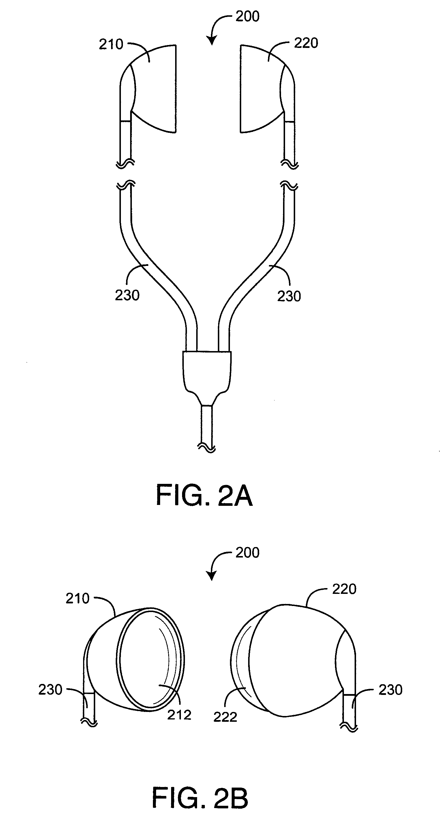
[0046]FIGS. 2A-B illustrate an ear bud embodiment of an ear sensor 200 having an emitter ear bud 210, a detector ear bud 220 and connecting cables 230. The emitter ear bud 210 has a generally concave surface for attachment to the back of an ear. The detector ear bud 220 has a generally convex surface 222 for attachment inside the ear at a concha site opposite the emitter ear bud 210. Sensor cables 230 are attached at the back of each ear bud having wires for electrical communications with a physiological monitor, such as a pulse oximeter. In particular, the emitter ear bud 210 includes wires for receiving emitter drive current from a monitor and the detector ear bud 220 includes wires for transmitting photodiode current to the monitor.

[0047]FIGS. 3A-B illustrate a flexible ear pad embodiment of an ear sensor 300 having an emitter pad 310, a detector pad 320 and corresponding cables 330. The sensor pads 310, 320 advantageously include a housing for each of the emitter pad 310 and the...


PUM


Abstract

An ear sensor provides a sensor body having a base, legs extending from the base and an optical housing disposed at ends of the legs opposite the base. An optical assembly is disposed in the housing. The sensor body is flexed so as to position the housing over a concha site. The sensor body is unflexed so as to attach the housing to the concha site and position the optical assembly to illuminate the concha site. The optical assembly is configured to transmit optical radiation into concha site tissue and receive the optical radiation after attenuation by pulsatile blood flow within the tissue.

Description

CROSS-REFERENCE TO RELATED APPLICATIONS[0001]The present application claims priority benefit under 35 U.S.C. §119(e) to U.S. Provisional Patent Application Ser. No. 61 / 152,964, filed Feb. 16, 2009, titled Ear Sensor, hereby incorporated by reference herein.BACKGROUND OF THE INVENTION[0002]Pulse oximetry systems for measuring constituents of circulating blood have gained rapid acceptance in a wide variety of medical applications, including surgical wards, intensive care and neonatal units, general wards, home care, physical training, and virtually all types of monitoring scenarios. A pulse oximetry system generally includes an optical sensor applied to a patient, a monitor for processing sensor signals and displaying results and a patient cable electrically interconnecting the sensor and the monitor. A pulse oximetry sensor has light emitting diodes (LEDs), typically one emitting a red wavelength and one emitting an infrared (IR) wavelength, and a photodiode detector. The emitters an...

Claims


Application Information

Patent Timeline
Patent Type & Authority Patents(United States)
IPC IPC(8): A61B5/1455
CPCA61B5/14552A61B5/6815A61B5/6817A61B5/6838A61B5/6867A61B5/0205A61B5/02427A61B5/0261A61B5/6816A61B5/1455
Inventor ABDUL-HAFIZ, YASSIRAL-ALI, AMMARFORREST, KEVINMASON, EUGENESCHMIDT, JOHNTA, VIRGINIA THANH
Owner JPMORGAN CHASE BANK NA
Why Eureka
Try Eureka