Lifting foil

a foil and foil technology, applied in the field of fluid dynamics, can solve the problems of not being fully satisfactory, and achieve the effects of reducing a dynamic pressure, increasing the dynamic pressure, and reducing the generation of initial spanwise fluid flow

Active Publication Date: 2013-03-05
HOUCK II RONALD G
View PDF22 Cites 3 Cited by
  • Summary
  • Abstract
  • Description
  • Claims
  • Application Information

AI Technical Summary

Benefits of technology

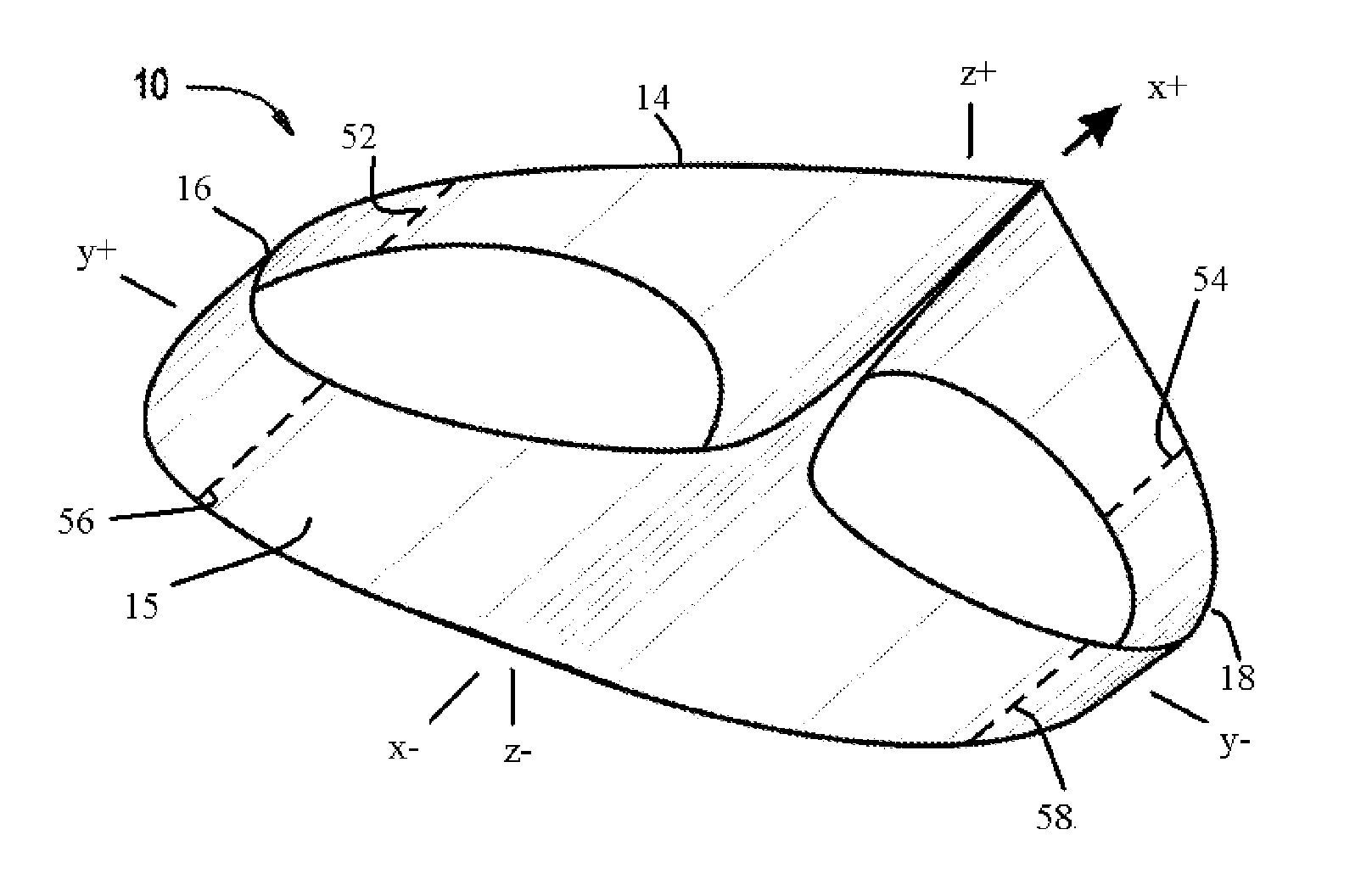
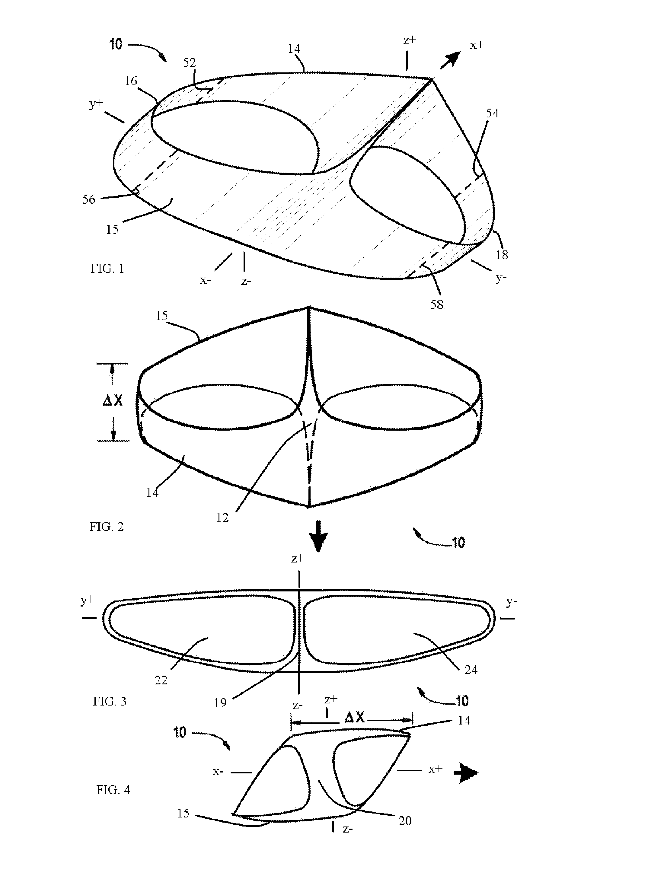
[0005]This invention is different than that of the present inventor's prior disclosed design and yields an unexpected and improved stability and result. Similar to the present inventor's prior design, there is provided a lifting foil configured generally in the form of an endless band having a plurality of exposed surfaces which meet at common boundary lines. Here, however, the lifting foil comprises a generally horizontal and leading upper course, a generally horizontal and trailing lower course parallel to and spaced apart from the upper course and a pair of opposed, vertically extending flow guides. A first one of these flow guides joins a first end of the upper course to a corresponding first end of the lower course, while a second flow guide joins a second end of the upper course to a corresponding second end of the lower course. The lower course configured with a main fuselage compartment.
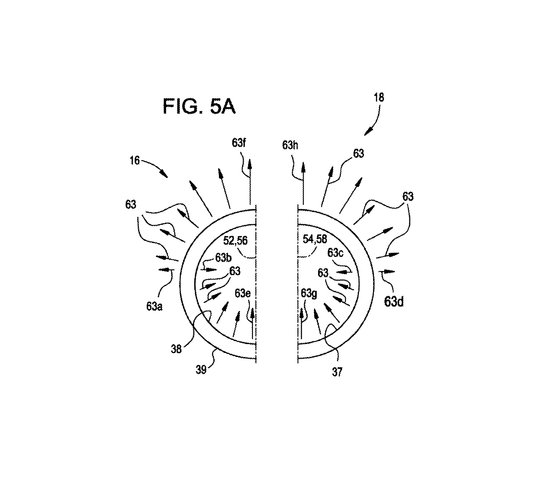
[0007]With the leading upper course so positioned in connection with the flow guides angled to the rear to connect with the trailing lower course, there is diminished generation of initial spanwise fluid flow by balancing the pressure at the upper starboard margin against the pressure at the lower starboard margin, and concomitantly balancing the pressure at the upper port margin against the pressure at the lower port margin without any fluid interference caused by the trailing lower course housing the fuselage. The pressure balancing is accomplished by configuring the starboard flow guides to have a cross section which will reduce a dynamic pressure from a maximum value at the upper starboard margin to a midpoint value of zero, while simultaneously increasing the dynamic pressure from a midpoint value of zero to a maximum value at the lower starboard margin. A similar process is carried out on the port side of the foil. Another aspect of the invention is to provide a leading upper course and a trailing course wherein the courses can have a range from positive to negative camber.
[0008]The lifting foil is unexpectedly provided with increased stability and controllability in flight. It is believed that the performance of the foil is enhanced by virtue of a generally uniform upper leading course providing an initial fluid direction and further aided by flow guides configured to stabilize the dynamic pressure at the ends of the upper and lower courses. This new design enhances the ability to achieve reduced flow of fluid in the spanwise direction and reduces the generation of drag-producing vortices.
[0009]It is therefore an object of the present invention to provide an apparatus and method for improving the dynamic performance of a lifting foil.
[0012]A still further object of the invention is to enhance and increase lift while minimizing drag penalty.
[0013]Other objects of the invention are to enhance and increase lift and decrease drag for very low speed flight, to reduce spanwise fluid flow in a lifting foil, to decrease aircraft drag and improve aircraft stability, as well as other and further objects and advantages as will be apparent from the following description, the accompanying drawings and the appended claims.

Problems solved by technology

In that patent it was explained that these vortices result from a span-wise flow of air from a relatively high pressure condition on the lower wing surface to a relatively low pressure condition on the upper wing surface and that the prior art attempted to numerous techniques for dealing with induced drag, but none are fully satisfactory.

Method used


Image

  • Lifting foil
  • Lifting foil
  • Lifting foil

Examples


Embodiment Construction

Nomenclature / Abbreviation

[0131]AP barometric pressure in mmHg[0132]AR aspect ratio[0133]a slope of lift curve[0134]acc acceleration[0135]a0 two dimensional lift-curve slope[0136]b length of semi-span[0137]CLU lift coefficient on the upper surface of a biplane[0138]C mean chord length[0139]CD coefficient of drag[0140]CDo drag coefficient at zero lift[0141]CL lift coefficient[0142]CLL lift coefficient on the lower wing of a biplane[0143]CLU lift coefficient on the upper wing of a biplane[0144]Cf skin friction coefficient[0145]Dend—plates plates endplates drag[0146]Dform form drag[0147]Di induced drag[0148]Dinterface interference drag[0149]Dparasite parasite drag[0150]Dskinfriction skin friction drag[0151]Dtotal total Drag force[0152]Dwings wing drag[0153]dP diameter of the particle[0154]di image diameter of the particle[0155]e span efficiency factor[0156]f″ number of lens[0157]g gap ratio to the chord[0158]h perpendicular distance[0159]L lift force[0160]L / D lift to drag ratio[0161]l t...


PUM


Abstract

A lifting foil having a lower trailing course having a margins and an upper leading course margins connected in a manner to enhance lift of the foil.

Description

[0001]This application claims the benefit of earlier filed provisional application 61 / 085,904 filed Aug. 4, 2008.BACKGROUND OF THE INVENTION[0002]This invention relates generally to the field of fluid dynamics with emphasis on aerodynamic drag phenomena. A particular object of the invention is to reduce energy losses suffered by an aircraft in flight due to induced drag. It is known that this particular type of drag is accompanied by a shedding of vortices from the tips of the wings.[0003]The present inventor discussed the details of drag issues surrounding wing tips in commonly owned U.S. Pat. No. 7,100,867 to Houck II. In that patent it was explained that these vortices result from a span-wise flow of air from a relatively high pressure condition on the lower wing surface to a relatively low pressure condition on the upper wing surface and that the prior art attempted to numerous techniques for dealing with induced drag, but none are fully satisfactory.[0004]While inventor accompl...

Claims


Application Information

Patent Timeline
Patent Type & Authority Patents(United States)
IPC IPC(8): B64C39/06
CPCB64C11/00B64C39/062
Inventor HOUCK, II, RONALD G.
Owner HOUCK II RONALD G
Why Eureka
Try Eureka