
Image contrast enhancement

a technology of contrast enhancement and image, applied in image data processing, color television, television systems, etc., can solve the problems of uneven illumination of subjects and difficult design of enhancement algorithms, and achieve the effect of easy adjustmen

Active Publication Date: 2007-02-15
ACD SYST INT
View PDF57 Cites 81 Cited by
  • Summary
  • Abstract
  • Description
  • Claims
  • Application Information

AI Technical Summary

Benefits of technology

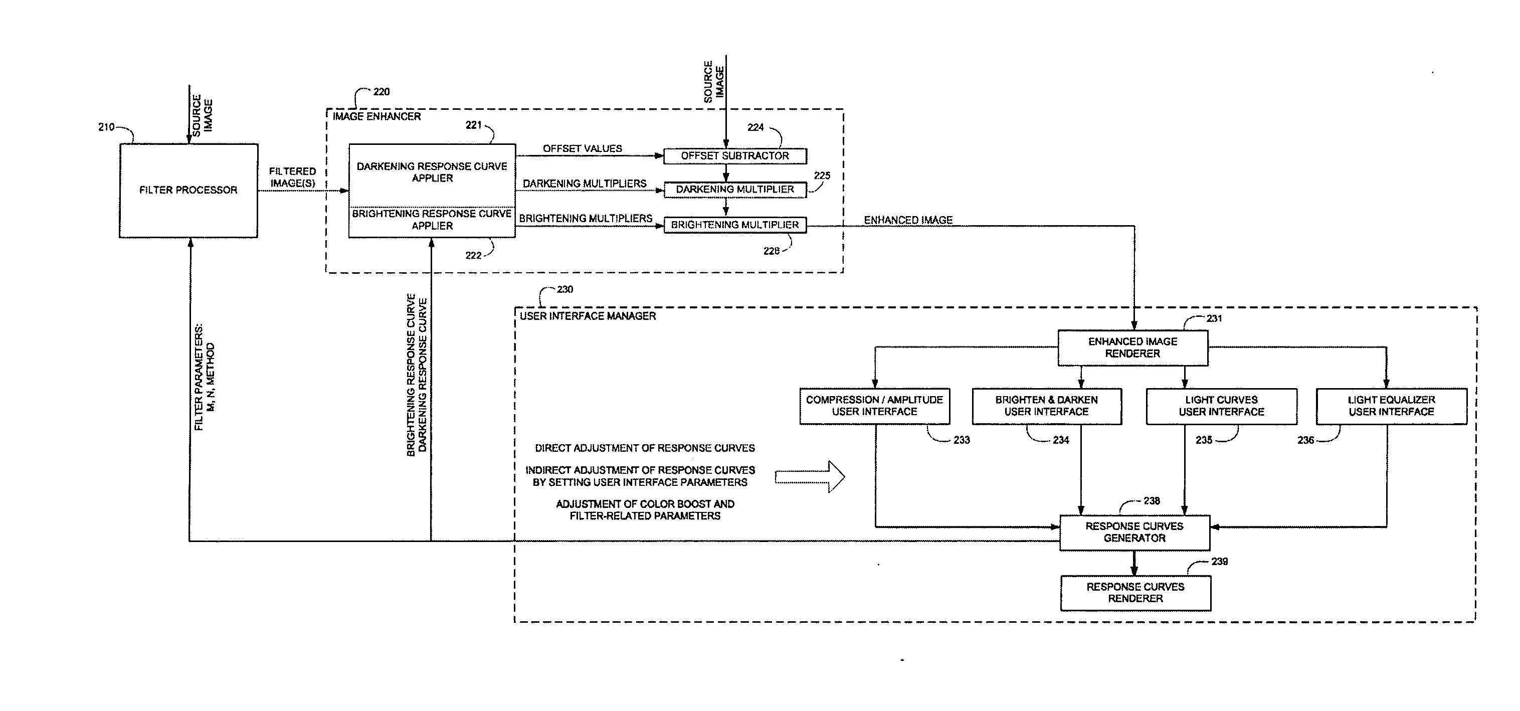
[0018] The present invention concerns a novel method and system for image enhancement that uses one or more filtered images to generate offsets and multipliers for adjusting pixel color values. Unlike prior art point-wise operations and prior art global enhancement operations, the image enhancement of the present invention is a local enhancement process, which is sensitive to characteristics of local pixel neighborhoods as well as to characteristics of an image as a whole. The image enhancement of the present invention can be controlled through adjustable user parameters that perform compression and amplitude adjustment for both shadow portions and highlight portions of an original image. These parameters are intuitive and easy to adjust.
[0019] The present invention can be implemented extremely efficiently, so as to achieve real-time performance whereby image enhancement is performed within a fraction of a second immediately upon adjustment of a user parameter, for multi-mega-pixel images captured by today's digital cameras. As such, a user is provided with continuous real-time feedback, which enables extremely accurate fine-tuning of the enhancement. Using the present invention, a user is able to instantly compare an enhanced image with a source image, and compare one enhanced image with another enhanced image.
[0020] Experimental results have shown that the present invention is robust, and yields excellent quality results, even for images where most of the detail is obscured in shadows or bright highlights.

Problems solved by technology

It is often the case that illumination of a subject is uneven, and a scene may appear two dark in some areas while too bright in other areas.
Requirements (ii) and (iv) generally conflict, since the ability to enhance a variety of different types of imagery generally requires a large number of complex adjustable parameters, where ease of use requires a small number of simple adjustable parameters, each of which is intuitive in its effect on the enhanced image.
This speed requirement, together with the proliferation of mega-pixel color images, makes design of an enhancement algorithm quite challenging.

Method used


Image

  • Image contrast enhancement
  • Image contrast enhancement
  • Image contrast enhancement

Examples


Embodiment Construction

The description that follows has much technical detail, and in order to clarify the presentation it is divided into sections as follows.

Sec. 1: Image Enhancement Phase One

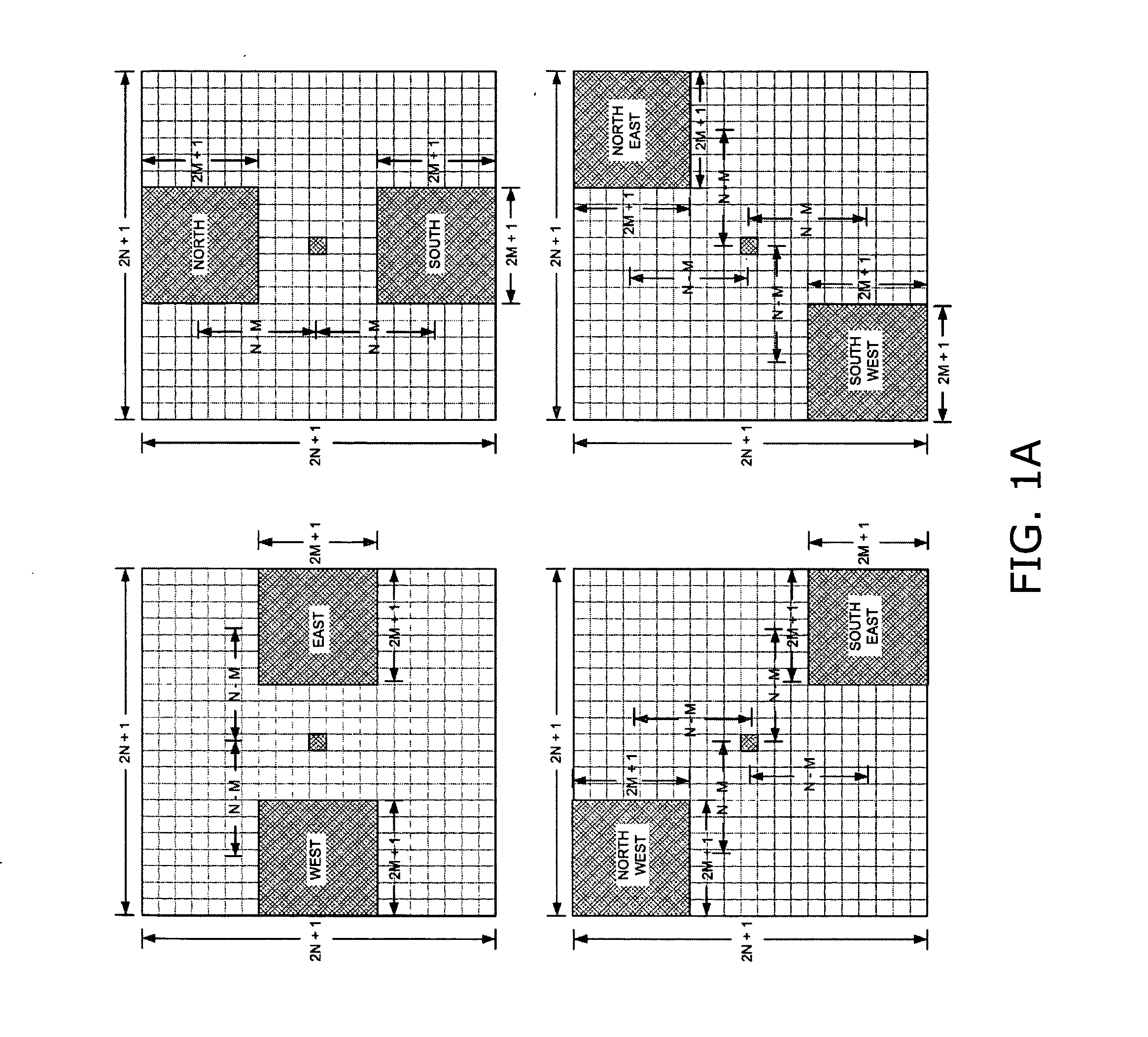
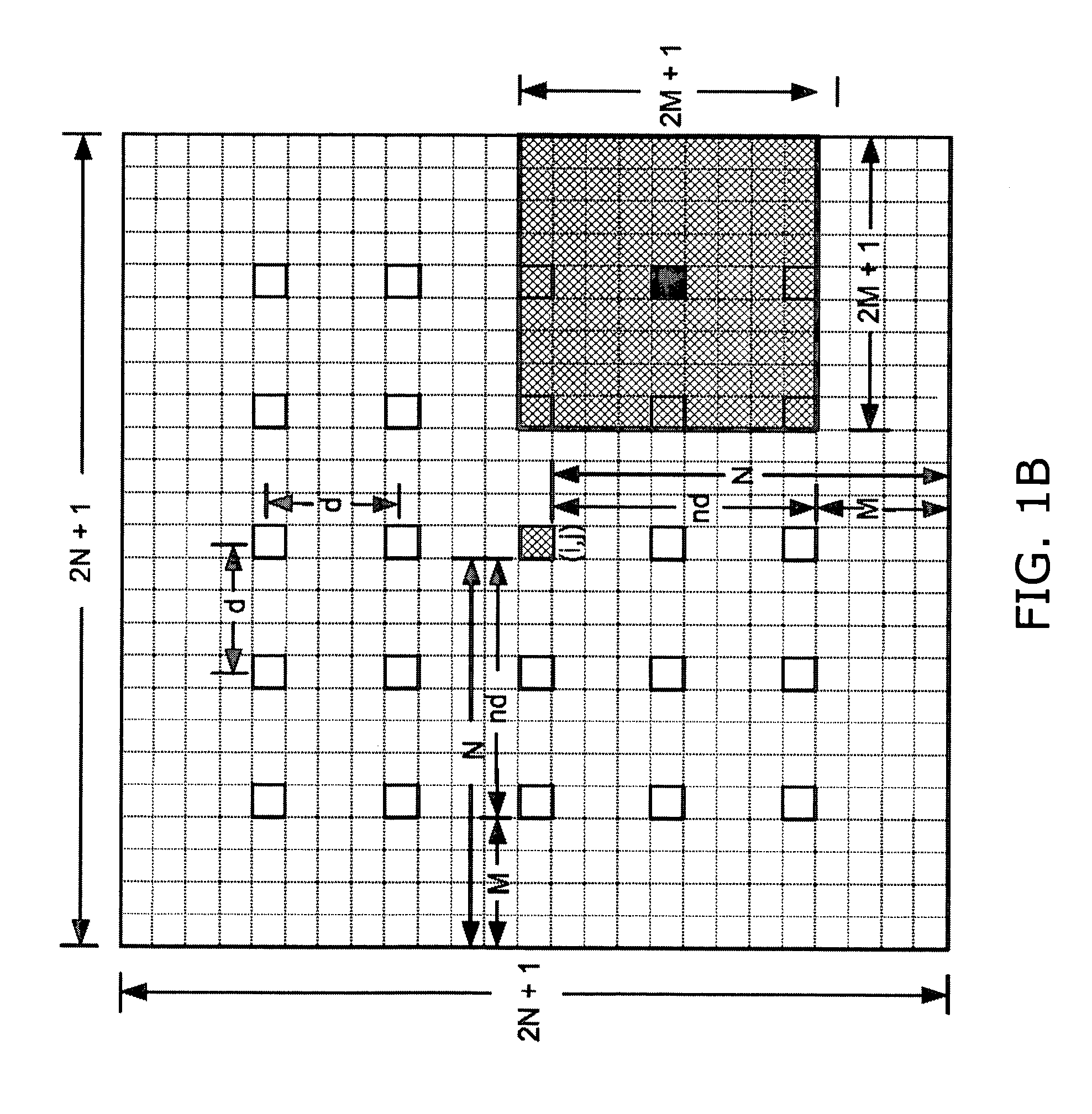
This section describes a first phase of image enhancement, related to generation of filtered images of an original source image, the filtered images being used to obtain local maximum and minimum color values.

[0112] Sec. 1.1: Modified Median Filter [0113] This subsection describes a variation of a median filter that is well suited for obtaining low frequency local color values for use with the response curves of the present invention.

[0114] Sec. 1.1.1: Modified Median Filter—Grayscale Source Image [0115] This subsection describes use of a median filter to derive a filtered image from a grayscale source image.

[0116] Sec. 1.1.2: Modified Median Filter with Filtered Luminance Image—Color Source Image [0117] This subsection describes use of a median filter to derive a filtered image from a color source image, b...


PUM


Abstract

A method for contrast enhancement for digital images, including filtering an original image having original color values, to generate a filtered image, receiving parameters for a response curve, the response curve being a function of color value that is user-adjustable, deriving local multipliers by applying the response curve to the filtered image, multiplying the original color values by the local multipliers, thereby generating a contrast-enhanced image from the original image. A system and a computer-readable storage medium are also described.

Description

CROSS REFERENCES TO RELATED APPLICATIONS [0001] This application is a continuation-in-part of assignee's pending application U.S. Ser. No. 11 / 106,339, filed on Apr. 13, 2005, entitled “Local Contrast Enhancement.”COMPUTER PROGRAM LISTING [0002] A portion of the disclosure of this patent document contains material which is subject to copyright protection. The copyright owner has no objection to facsimile reproduction by anyone of the patent document or the patent disclosure, as it appears in the Patent & Trademark Office patent file or records, but otherwise reserves all copyright rights whatsoever. [0003] Applicant has submitted herewith Computer Program Listings which are included as Appendix A through Appendix G, on a compact disc, and this information is incorporated herein by reference to the compact disc. The two compact discs are identical and include a “Copy 1” and “Copy 2” and are labeled respectively. The two discs contain the following appendices: [0004] Appendix A, entitl...

Claims


Application Information

Patent Timeline
Patent Type & Authority Applications(United States)
IPC IPC(8): G06K9/40
CPCG06T5/008G06T5/20G06T2207/10024
Inventor HOOPER, DAVID SHELDON
Owner ACD SYST INT
Learn More