
Device and method for correcting and stabilizing a deviating curvature of a spinal column
a technology of deviating curvature and spinal column, which is applied in the field of spinal column deviating curvature correction and stabilization devices, can solve the problems of inconvenient long time, several drawbacks of prior-art construction, and one of the most difficult complications of structural scolioses
- Summary
- Abstract
- Description
- Claims
- Application Information
AI Technical Summary
Benefits of technology
Problems solved by technology
Method used
Image

Examples
Embodiment Construction
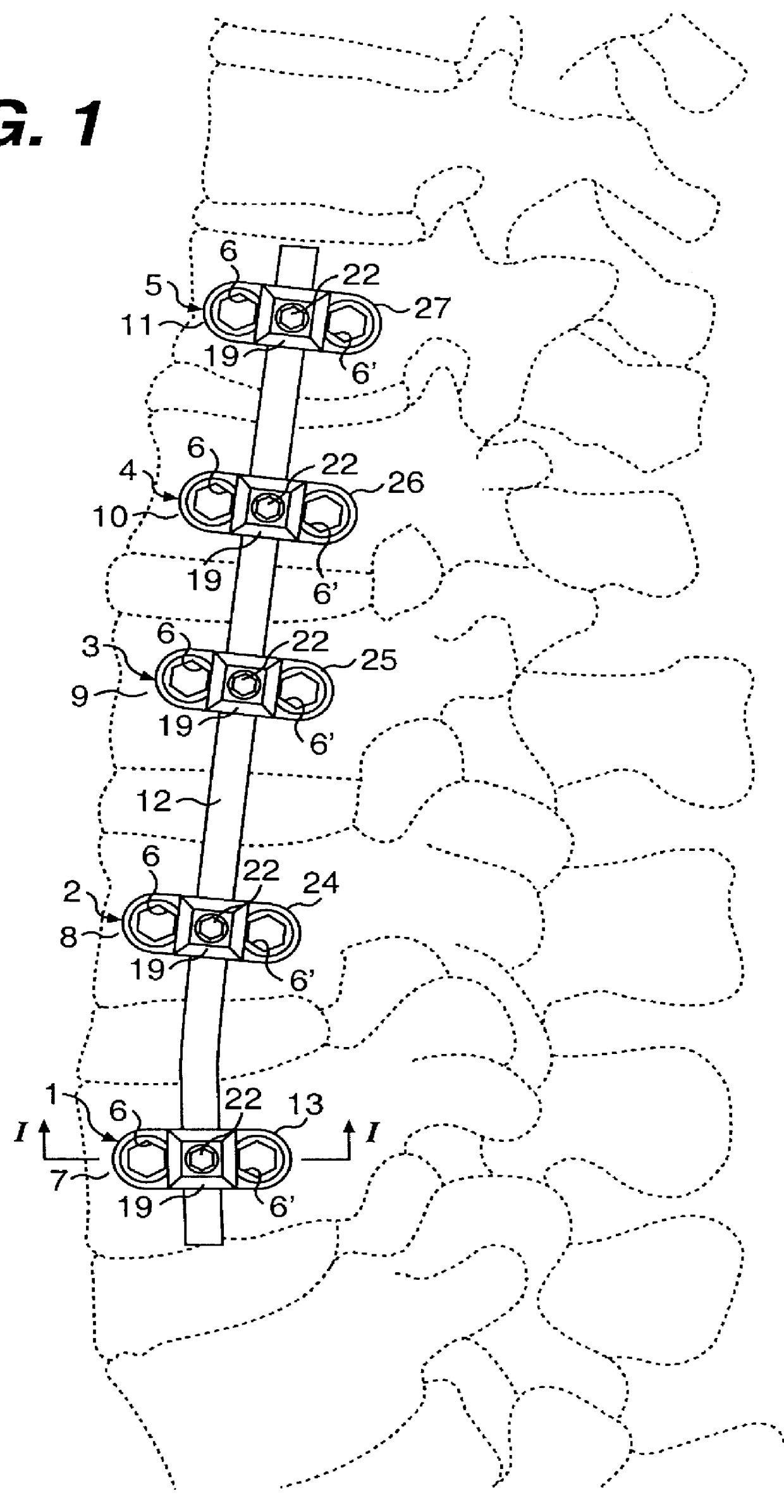
FIG. 1 shows the inventive device in mounted stated on a spinal column. In the embodiment shown, the device comprises five brace holders 1, 2, 3, 4, 5, two pedicel screws 6, 6' for securing the respective brace holders 1, 2, 3, 4, 5 on a vertebral body 7, 8, 9, 10, 11, and an elongate plate-shaped brace 12. Normally, a corresponding device is also arranged on the opposite side of the spinal column.
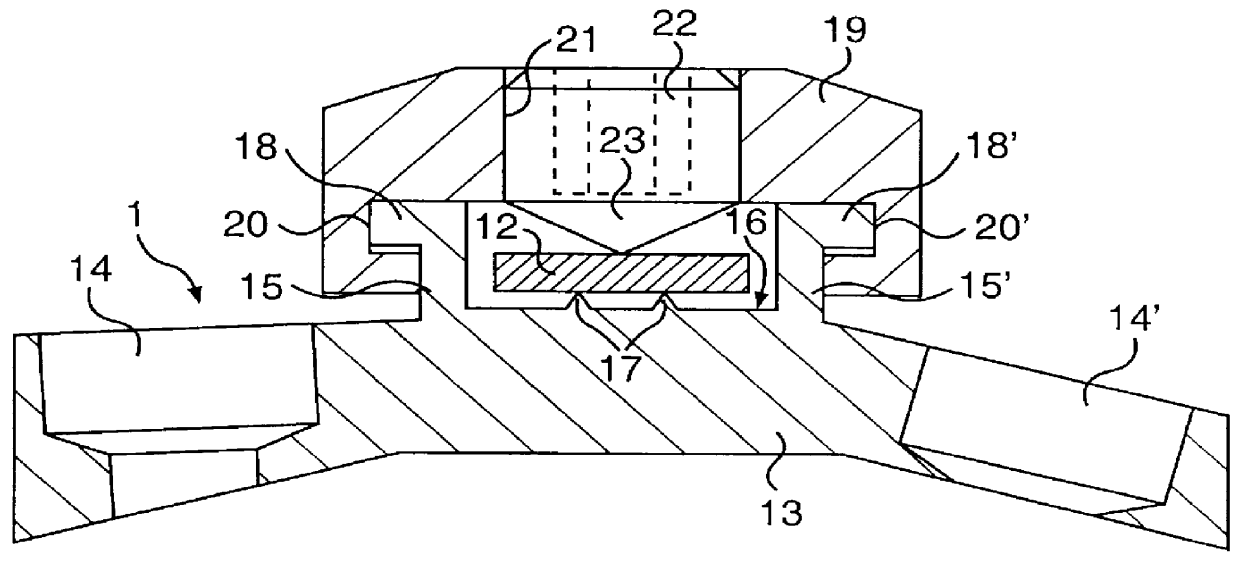
The brace holder 1 has, as shown in FIG. 2, a frame comprising a long and narrow base plate 13, which in its end portions has a through mounting hole 14, 14' for receiving a pedicel screw 6, 6'. The underside of the base plate 13 is of a shape that essentially conforms with the outer surface of the vertebral body 7. On the upper side of the base plate 13, there are formed between the through mounting holes 14, 14' two flanges 15, 15' which project at right angles from the base plate 13 and which extend across the width of the base plate 13 and define, between themselves, a space and a flat...
PUM
 Abstract
Description
Claims
Application Information