
High efficiency, monolithic multijunction solar cells containing lattice-mismatched materials and methods of forming same

a solar cell, high efficiency technology, applied in the direction of basic electric elements, electrical apparatus, semiconductor devices, etc., can solve the problems of reducing the performance of the upper subcell, reducing the quality and reducing the performance of the lower subcell, so as to achieve a wide range of performance and reduce strain. , the effect of adjusting or optimizing the performan

Active Publication Date: 2005-10-04
OSTENDO TECH INC
View PDF12 Cites 302 Cited by
  • Summary
  • Abstract
  • Description
  • Claims
  • Application Information

AI Technical Summary

Benefits of technology

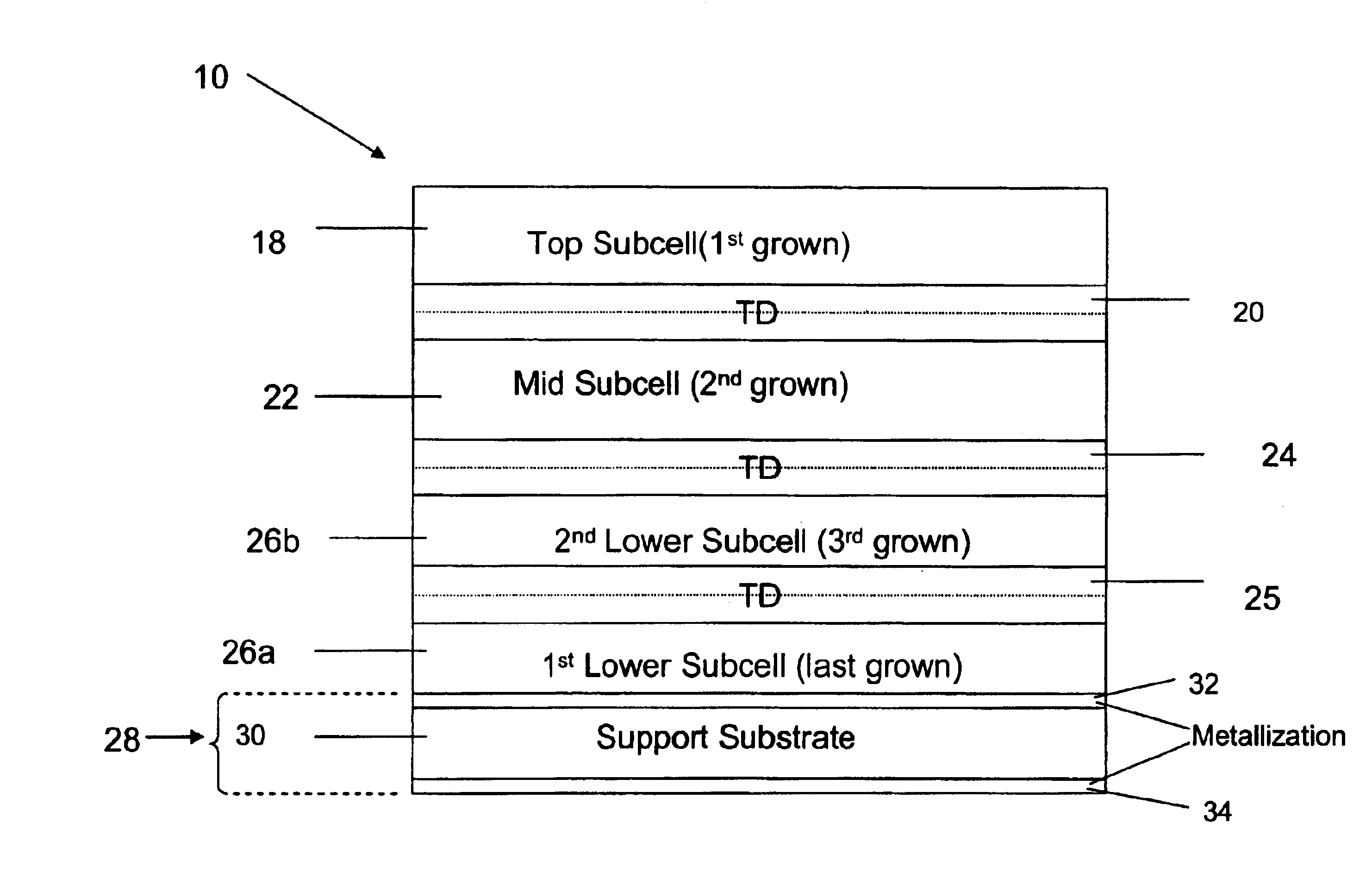
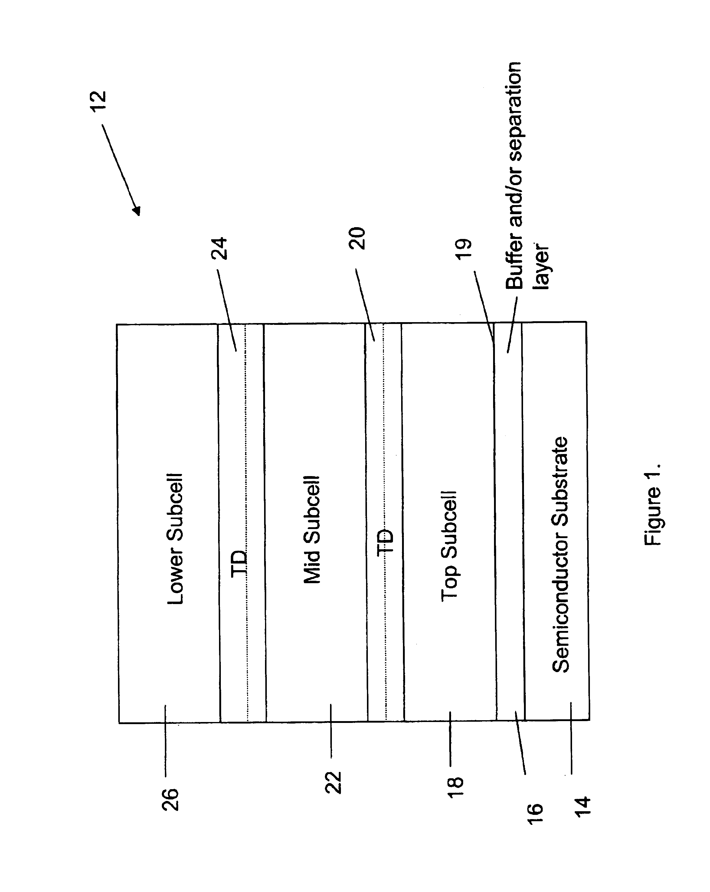
[0015]In certain non-limiting embodiments, the multijunction cell may be formed by growing the subcells in reverse order on, for example, a GaAs or Ge substrate. With this reverse growth process, the upper subcell(s) can be fabricated to have high performance by having atomic lattice spacing closely matched to that of the growth substrate. Lower subcells can be included with appropriate band gap, but with lattice spacing mismatched to the other subcells. Similarly, the upper cell(s) can have performance that is adjusted or optimized, while the lattice-mismatch in the lower subcell(s) can be addressed separately. The lower subcell(s), grown later than the upper two cells, can be separately tailored or optimized to provide the desired electrical output. Lattice-grading layers, e.g., of InGaAs, may be used as well as temperature-cycling to reduce strain. The internal design of the lower subcell(s) can also be appropriately selected or optimized, in layer thicknesses, and impurity concentrations and gradients.

Problems solved by technology

Attempts to grow lower subcells in this band gap range on a GaAs or Ge substrate have not been successful, because the lattice-mismatch, about 2% with compounds like In(x)Ga(1−x)As where x˜0.3, reduced the quality and performance of the lower subcell.
The lattice mismatch also degraded the performance of the upper subcells even if attempts were made to compensate for the lattice mismatch.
Inclusion of additional elements such as nitrogen or boron in the InGaAs in the lower subcell maintained the band gap and changed the lattice spacing to match the substrate, but the added elements led to very poor electronic quality.
The decreased current density in the series-connected subcells severely limited the cell performance, even if the upper subcells had good performance.

Method used


Image

  • High efficiency, monolithic multijunction solar cells containing lattice-mismatched materials and methods of forming same
  • High efficiency, monolithic multijunction solar cells containing lattice-mismatched materials and methods of forming same
  • High efficiency, monolithic multijunction solar cells containing lattice-mismatched materials and methods of forming same

Examples


Embodiment Construction

[0026]Multi-junction solar cells may comprise a plurality of subcells that convert solar radiation into electrical energy. In various preferred multi-junction solar cells, the different subcells absorb different spectral components of the solar spectrum such that a large portion of the spectrum is absorbed. In this manner, the conversion of optical energy into electrical energy is thereby increased.

[0027]The subcells preferably comprise semiconductor material having different band gaps with correspondingly different spectral absorption cutoff wavelengths. The plurality of subcells are preferably stacked such that light is absorbed by each of the subcells. In particular, in certain embodiments, higher band gap layers are stacked on lower band gap layers such that shorter wavelength light is absorbed by the higher band gap layers and longer wavelengths are transmitted therethrough. These longer wavelengths are absorbed by the lower band gap layers beneath the higher band gap layers.

[0...


PUM


Abstract

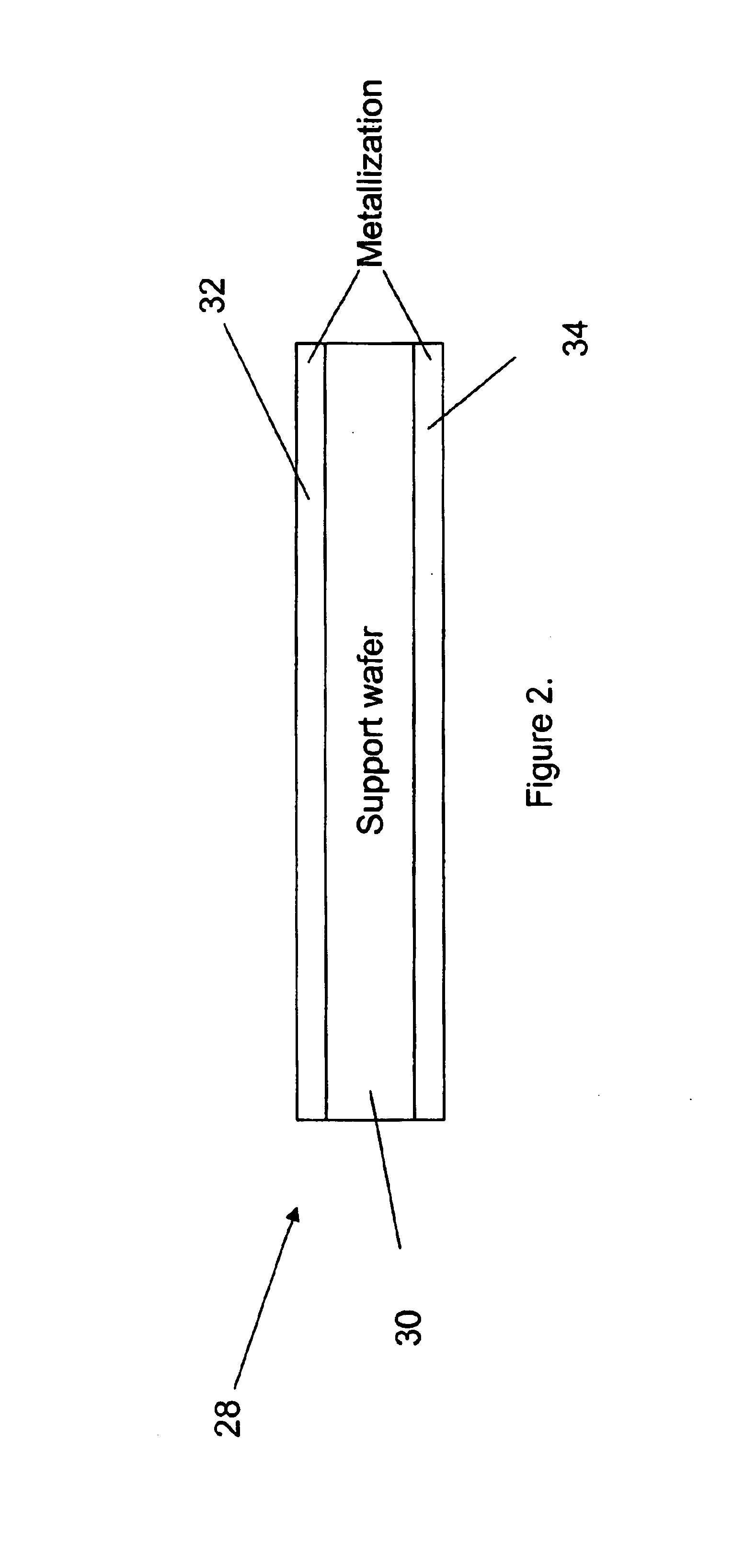
In one embodiment, a method of forming a multijunction solar cell having lattice mismatched layers and lattice-matched layers comprises growing a top subcell having a first band gap over a growth semiconductor substrate. A middle subcell having a second band gap is grown over the top subcell, and a lower subcell having a third band gap is grown over the middle subcell. The lower subcell is substantially lattice-mismatched with respect to the growth semiconductor substrate. The first band gap of the top subcell is larger than the second band gap of the middle subcell. The second band gap of the middle subcell is larger than the third band gap of the lower subcell. A support substrate is formed over the lower subcell, and the growth semiconductor substrate is removed. In various embodiments, the multijunction solar cell may further comprise additional lower subcells. A parting layer may also be provided between the growth substrate and the top subcell in certain embodiments. Embodiments of this reverse process permit the top and middle subcells to have high performance by having atomic lattice spacing closely matched to that of the growth substrate. Lower subcells can be included with appropriate band gap, but with lattice spacing mismatched to the other subcells. The reduced performance caused by strain resulting from mismatch can be mitigated without reducing the performance of the upper subcells.

Description

PRIORITY APPLICATION[0001]This application claims priority under 35 U.S.C. §119(e) from U.S. Provisional Patent Application No. 60 / 431,334, entitled “Method for Forming a High Efficiency Monolithic Multijunction Solar Cell Containing Lattice-Mismatched Materials” filed Dec. 5, 2002, which is hereby incorporated by reference herein in its entirety.BACKGROUND OF THE INVENTION[0002]1. Field of the Invention[0003]This invention relates in one embodiment to a high efficiency monolithic multijunction solar cell comprising lattice-mismatched materials, and a method for making the same.[0004]2. Description of the Related Art[0005]To date, the highest conversion efficiency achieved for monolithically-grown, series-connected multijunction solar cells has been obtained using semiconductors with atomic lattice spacing closely matched to that of the growth substrate. In particular, the highest conversion efficiency multijunction solar cells have been formed using Group III-V semiconductors with ...

Claims


Application Information

Patent Timeline
Patent Type & Authority Patents(United States)
IPC IPC(8): H01L21/302H01L21/02H01L21/461H01L31/0264H01L31/0687
CPCH01L31/0687H01L31/06875H01L31/1892Y02E10/544Y02E10/547
Inventor ILES, PETER A.HO, FRANK F.YEH, YEA-CHUAN M.
Owner OSTENDO TECH INC
Learn More