
Method of and apparatus for multiplying raster scanning lines by modulating a multi-cavity laser diode

a laser diode and multi-cavity technology, applied in the field of bar code symbol reading system improvement, can solve the problems of increasing manufacturing costs and complicated design, and achieve the effect of improving laser scanning characteristics

Active Publication Date: 2014-03-25
METROLOGIC INSTR INC
View PDF40 Cites 759 Cited by
  • Summary
  • Abstract
  • Description
  • Claims
  • Application Information

AI Technical Summary

Benefits of technology

[0008]Accordingly, it is a primary object of the present disclosure to provide a new and improved way of and means for generating multi-line laser scanning patterns with improved laser scanning characteristics, while avoiding the shortcomings and drawbacks of prior art apparatus and methodologies.
[0013]Another object is to provide a new and improved hand-supportable laser scanning reading bar code symbol reading system, capable of selectively generating a single line laser scanning pattern, or a multiple-line raster-type laser scanning pattern, as required by the application at hand, to read high density 2D stacked bar code symbologies with improved levels of performance.

Problems solved by technology

However, the number of scan lines in the raster pattern of U.S. Pat. No. 7,077,324 is limited to the number of beam splitters and reflectors which complicates the design and increases manufacturing costs.

Method used


Image

  • Method of and apparatus for multiplying raster scanning lines by modulating a multi-cavity laser diode
  • Method of and apparatus for multiplying raster scanning lines by modulating a multi-cavity laser diode
  • Method of and apparatus for multiplying raster scanning lines by modulating a multi-cavity laser diode

Examples


Embodiment Construction

[0027]Referring to the figures in the accompanying Drawings, the illustrative embodiment of the digital imaging system will be described in greater detail, wherein like elements will be indicated using like reference numerals.

Overview of Method of and Apparatus of the Present Disclosure

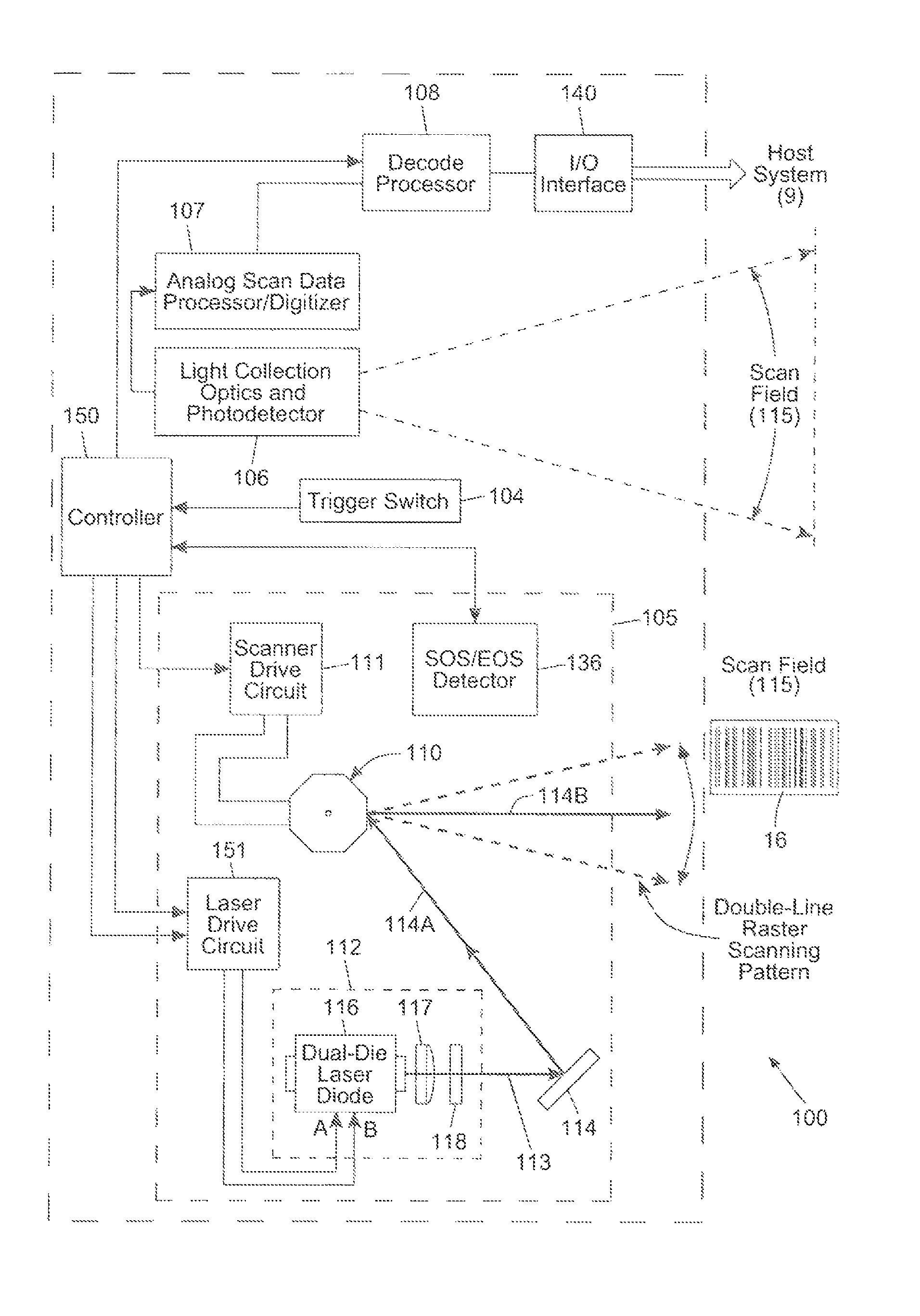
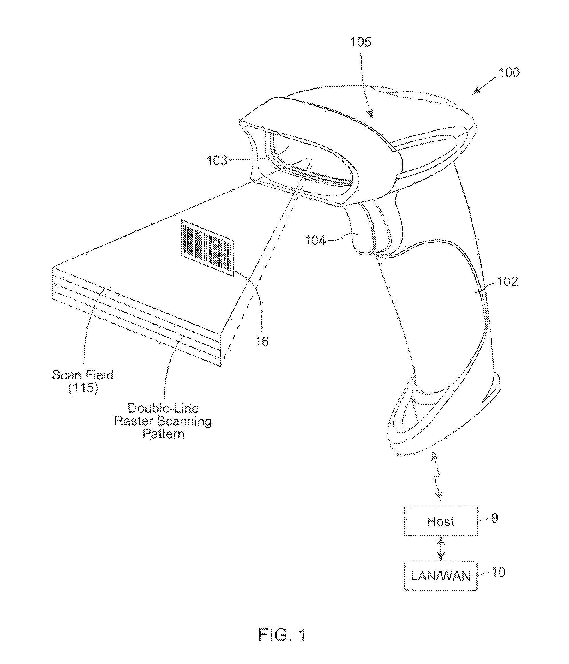
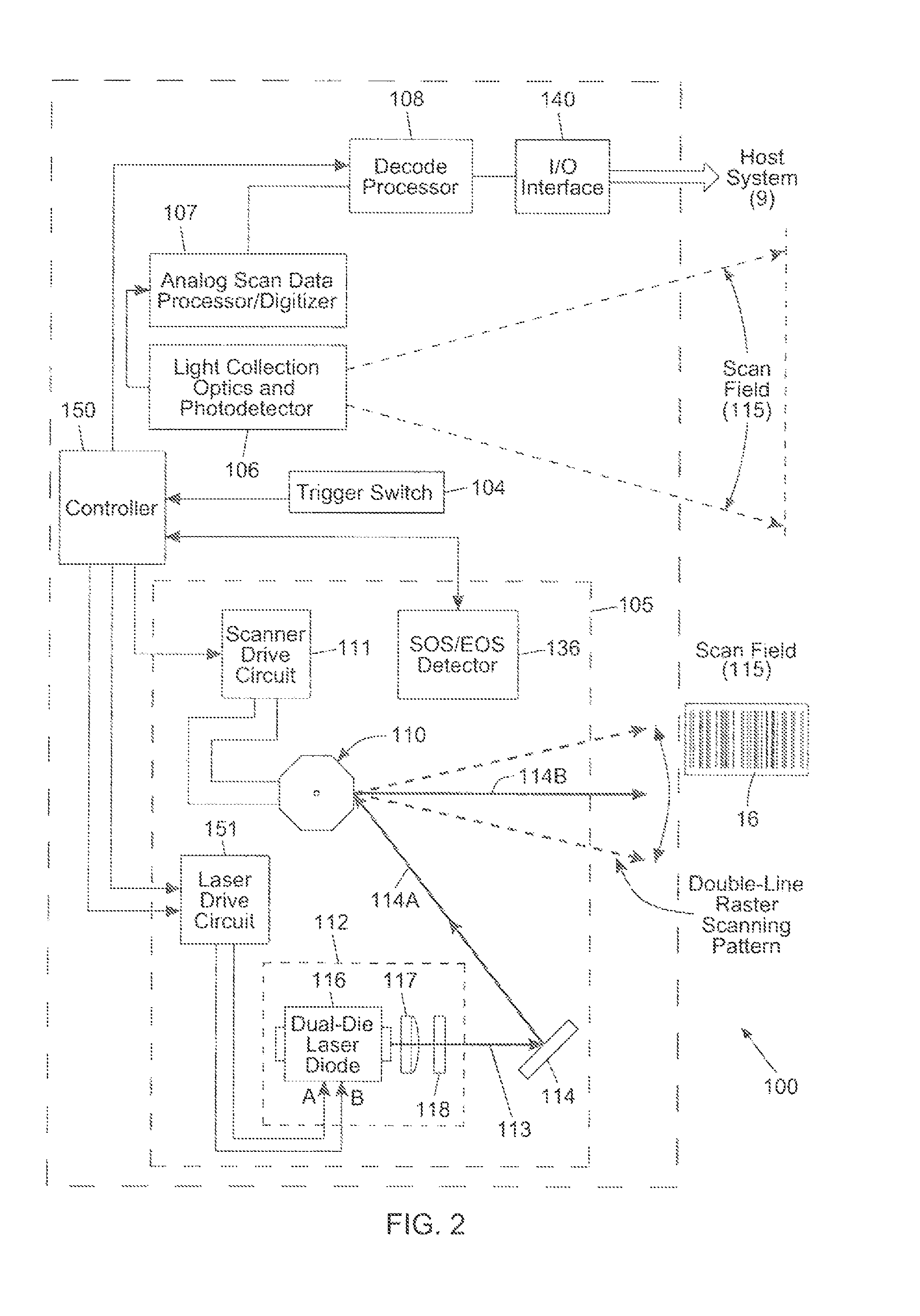
[0028]A method of and apparatus for generating a multiple raster-type scanning pattern by modulating a multi-cavity laser diode in such a way that it sequentially generates different laser beams synchronously during different laser scanning cycles, while the output laser beams are directed incident upon a rotating polygonal laser scanning element. The system does not require additional moving parts beyond the rotating polygon scanning element so as to reduce complexity and simplify construction of the laser scanning mechanism.

[0029]Specifically, the method involves performing the following steps in a housing: (a) sequentially activating and driving the laser cavities of a multi-cavity laser diode so a...


PUM


Abstract

A method of and apparatus for generating a multiple raster-type scanning pattern by modulating a multi-cavity laser diode in such a way that it sequentially generates different laser beams synchronously during different laser scanning cycles, while the output laser beams are directed incident upon a rotating polygonal laser scanning element. The system does not require additional moving parts beyond the rotating polygon scanning element so as to reduce complexity and simplify construction of the laser scanning mechanism.

Description

BACKGROUND OF DISCLOSURE[0001]1. Field of Disclosure[0002]The present disclosure relates to improvements in bar code symbol reading systems employing laser scanning patterns having improved characteristics.[0003]2. Brief Description of the State of Knowledge in the Art[0004]Bi-optic laser scanners require the projection of several scan lines at multiple angles and directions to ensure code coverage and increased probability of a successful scan. A raster pattern can be generated in such a way that multiply the parallel scan lines of the raster scanning pattern. This is typically accomplished using multi-faceted reflective polygons that include various facet angles. For each additional raster line, scan performance will likely increase.[0005]U.S. Pat. No. 7,077,324 to Tien discloses a multi-line raster-type barcode laser scanner with no moving parts. The laser scanner includes a light source, a light condensing lens and a linear light receiver. The system employs at least one beam sp...

Claims


Application Information

Patent Timeline
Patent Type & Authority Patents(United States)
IPC IPC(8): G06K9/36G06K7/10G02B26/00
CPCG06K7/10613G06K7/10564G06K7/1096G06K7/1091G06K7/10673G06K7/10574
Inventor KEARNEY, SEAN, PHILIP
Owner METROLOGIC INSTR INC
Learn More