Wiper blade for windshields, especially automobile windshields, and method for the production thereof

a technology for windshields and blades, which is applied in the field of windshield wiper blades, can solve the problems of affecting the quality of windshield wipers, affecting the service life of vehicles, and affecting the service life of vehicles, and achieves the effects of favorable wiping results, favorable wiping quality, and convenient production

Inactive Publication Date: 2005-01-04
ROBERT BOSCH CORP
View PDF11 Cites 101 Cited by
  • Summary
  • Abstract
  • Description
  • Claims
  • Application Information

AI Technical Summary

Benefits of technology

The wiper blade according to the invention, with the features of the main claim, has the advantage of an entirely favorable wiping quality because among other things, a rattling of the wiper blade across the window—the so-called slip-stick effect—is prevented. This results from the knowledge that for the slip-stick effect, attention must be paid particularly to the lateral deflection angle and less so to the absolute lag, i.e. the absolute deflection of the tips under stress. It is therefore advantageous if the wiper blade is designed so that the lateral deflection of the ends of the wiper blades, which lag behind during operation, does not exceed a lateral deflection angle of a particular magnitude. From the quantity discovered for this angle, important parameters can then be derived for the wiper blade, which have a simple relation to one another and which, in this relation, should not exceed an upper limit of 0.009. With the aid of this relation and the upper limit indicated, cross sectional profiles for the support element can be very simply determined, which then produce a favorable wiping result. In particular, wiper blades with a constant cross section over their lengths are particularly easy to produce in this manner.
The wiping quality increases further if the proportion of the product of the contact force and the square of the length to the product of 48 times the elasticity modulus of the support element and the Izz moment of inertia does not exceed an upper limit of 0.005.
The wiper blade according to the invention has the advantage that only one parameter has to be varied in order to adjust the outwardly decreasing contact force distribution. The curvature or the curvature progression along the support element can be preset in freely programmable bending machines. As a result, short trial runs can also be carried out to optimize the contact force distribution and therefore the curvature progression rapidly and without a great deal of expense. It is particularly advantageous if the coordinate that governs the curvature progression extends along the inertial element. This eliminates the need for complex reverse calculations in a Cartesian coordinate system in which each change in a position x requires a shifting of the subsequent “x values”.
Even with complex window curvature progressions, the wiping quality can be increased by presetting the contact force distribution to particular support points. It is nevertheless possible to design the wiper blade without complex calculations. The curvature progression can be essentially predetermined and can be optimized by means of simple trials. An excellent wiping quality is assured as long as the prerequisites are met that the contact force distribution that prevails when the wiper blade is pressed against the window to be wiped is greater in a region approximately halfway between the center and the end of the wiper blade than it is at the end of the wiper blade.

Problems solved by technology

The uniform pressure distribution over the entire wiper blade length that is sought in both cases, however, leads to an abrupt flipping over of the wiper lip, which belongs to the wiper blade and performs the actual wiping function, over its entire length, from its one drag position into its other drag position when the wiper blade reverses its working direction.
The abrupt flipping over of the wiper lip, however,—which is inevitably connected with an up and down motion of the wiper blade—generates an undesirable tapping noise.
In addition, the matching of the support element tension to the desired pressure distribution, which differs from case to case, is problematic with spherically curved windows.
The other data relate to an unstressed wiper blade so that it is hardly possible to draw conclusions as to the quality of a wiper blade during operation.
In addition, putting the teaching of the known prior art to use turns out to be difficult since the available parameters cannot be applied directly to wiper blades to be newly manufactured.

Method used


Image

  • Wiper blade for windshields, especially automobile windshields, and method for the production thereof
  • Wiper blade for windshields, especially automobile windshields, and method for the production thereof
  • Wiper blade for windshields, especially automobile windshields, and method for the production thereof

Examples


Embodiment Construction

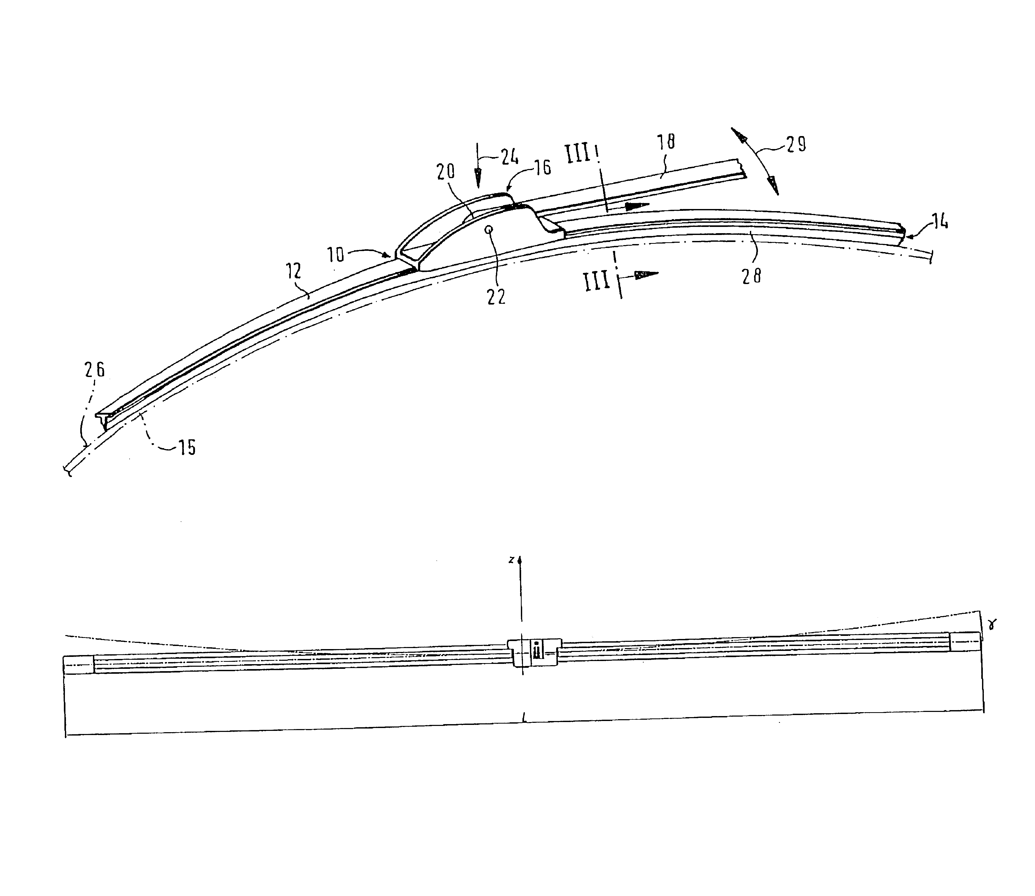
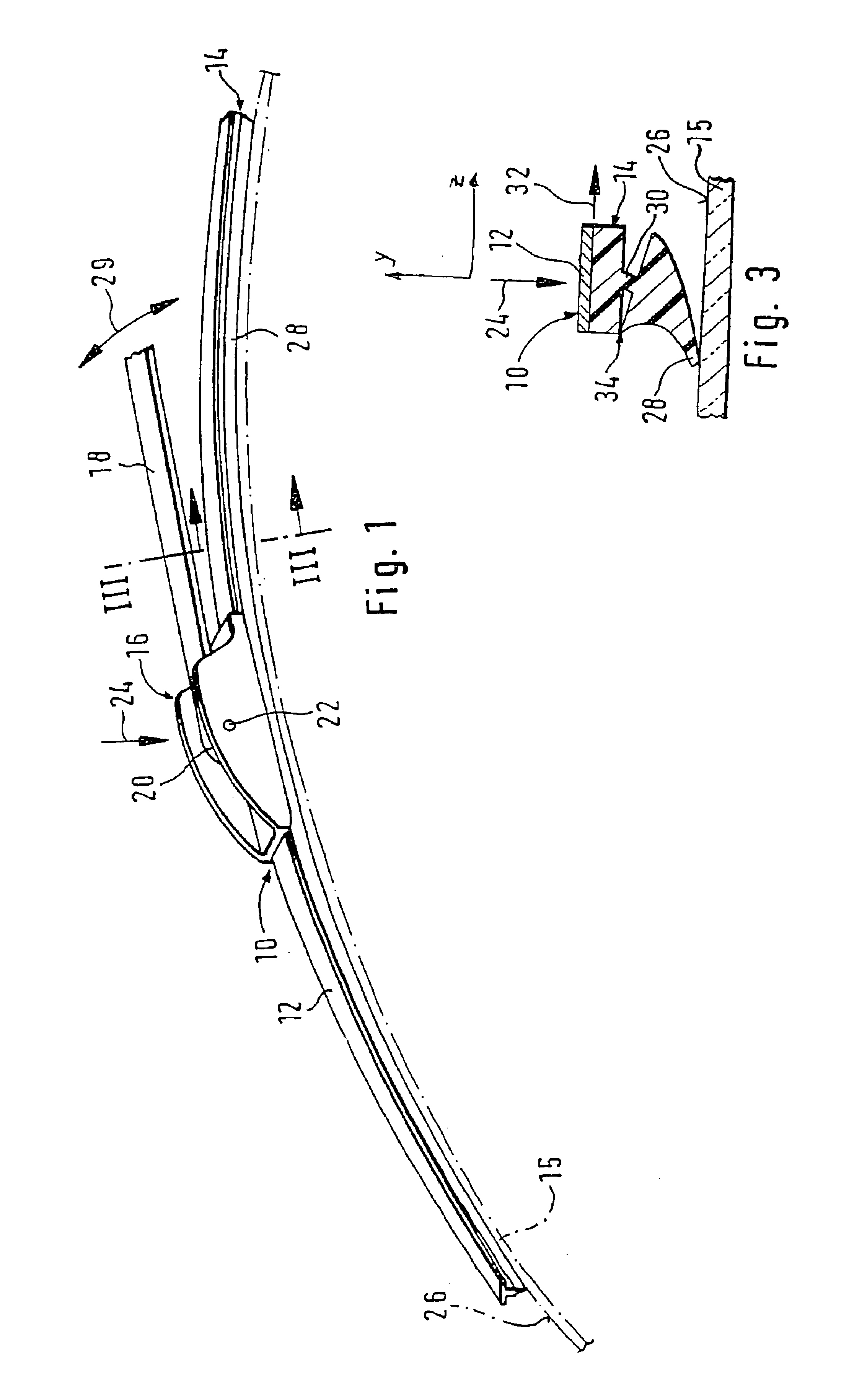
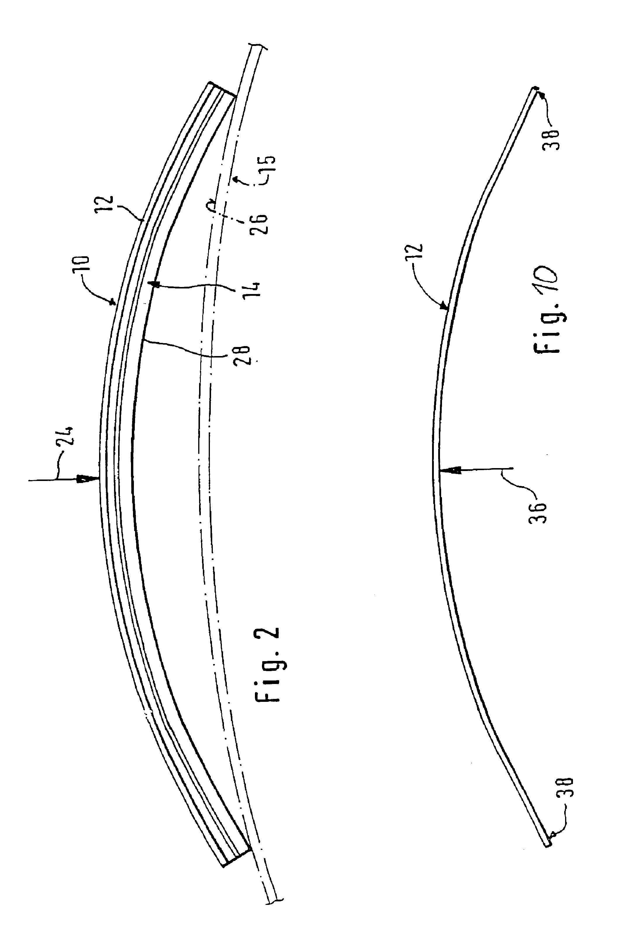
A wiper blade 10 shown in FIG. 1 has an elongated, spring elastic support element 12, which is also referred to as a flat bar, for a wiper strip 14, which is shown separately in FIG. 10. As shown in FIGS. 1, 3, and 4, the support element 12 and the wiper strip 14 are connected to each other with their longitudinal axes parallel. On the top side of the support element 12 remote from the window 15 to be wiped—shown with dot-and-dash lines in FIG. 1—, there is a connecting mechanism in the form of a connecting device 16 which can detachably connect the wiper blade 10 to a driven wiper arm 18 that is guided on the body of the motor vehicle. The elongated rubber elastic wiper strip 14 is disposed on the underside of the support element 12 oriented toward the window 15.

A hook, which serves as a counterpart connection means, is formed onto the free end 20 of the wiper arm 18 and engages a pivot bolt 22 that is part of the connecting device 16 of the wiper blade 10. The securing between the...


PUM


Abstract

The invention relates to a wiper blade for windshields, especially automobile windshields, comprising at least one support element, a support element (12), a wiper strip (14) and connecting means (16) for a wiper arm (18). The support element (12) is a long flat rod to which the wiper strip (14) and the connecting means (16) are fixed. According to the invention, the flat rod has a cross-sectional profile (40), whereby Fwf*L2 / 48*E*Izz<0.009 when Fwf is the pressure force exerted on the wiper blade or the pressure force for which the wiper blade was originally intended, L represents the length of the wiper blade, E stands for the elasticity module of the flat rod material and Izz is the moment of inertia of the cross-sectional profile around the z axis (perpendicular to an s axis associated with the flat rod and perpendicular to the y axis).

Description

BACKGROUND OF THE INVENTIONIn wiper blades of the present invention, the support element should assure a predetermined distribution of the wiper blade pressing force—often also called pressure—applied by the wiper arm against the window, over the entire wiping zone that the wiper blade sweeps across. Through an appropriate curvature of the unstressed support element—i.e. when the wiper blade is not resting against the window—the ends of the wiper strip, which is placed completely against the window during the operation of the wiper blade, are loaded in the direction of the window by the support element, which is then under stress, even when the curvature radii of spherically curved vehicle windows change in every wiper blade position. The curvature of the wiper blade must therefore be slightly sharper than the sharpest curvature measured in the wiping zone of the window to be wiped. The support element thus replaces the costly support bracket design that has two spring strips dispos...

Claims


Application Information

Patent Timeline
Patent Type & Authority Patents(United States)
IPC IPC(8): B60S1/38
CPCB60S1/38B60S1/3874B60S1/3875
Inventor DE BLOCK, PETER
Owner ROBERT BOSCH CORP
Why Eureka
Try Eureka