Eureka AIR delivers breakthrough ideas for toughest innovation challenges, trusted by R&D personnel around the world.

Windscreen wiper device

A technology for automobiles and wiper arms, which is applied in vehicle cleaning, vehicle maintenance, transportation and packaging, and can solve the problem of low risk of pedestrian injury

Inactive Publication Date: 2012-01-11
ROBERT BOSCH GMBH
View PDF0 Cites 0 Cited by
  • Summary
  • Abstract
  • Description
  • Claims
  • Application Information

AI Technical Summary

Problems solved by technology

However, this deformation distance is still too small to reduce the risk of injury to pedestrians.

Method used


Image

  • Windscreen wiper device
  • Windscreen wiper device
  • Windscreen wiper device

Examples


Embodiment Construction

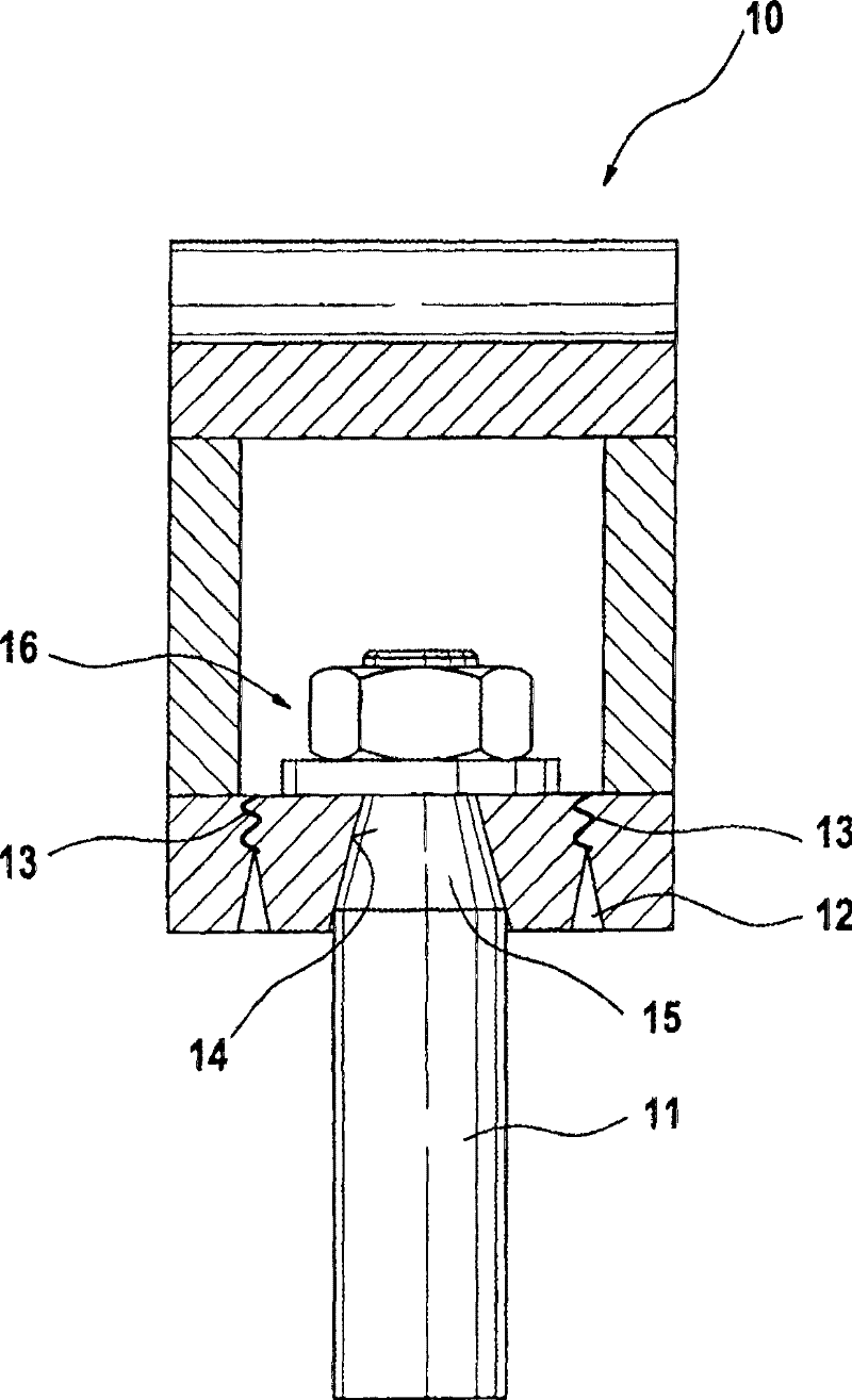
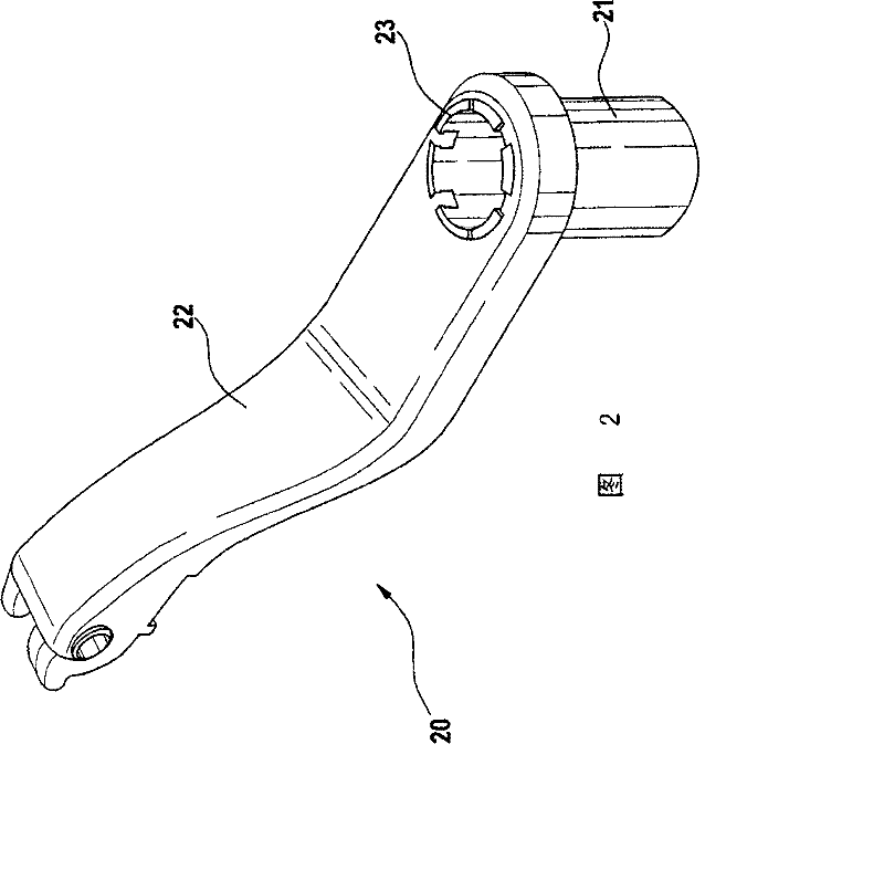
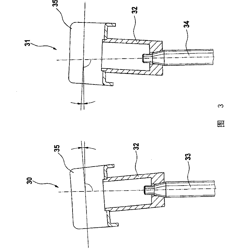
[0021] figure 1 A fastening part 10 of a windshield wiper system, which is not shown in detail here, is shown. The fastening part 10 connects a wiper arm, not shown in detail here, with a wiper shaft 11 . The fixture is a hollow cylinder. The fastening part 10 has, on the side facing the wiper shaft 11 , a desired breaking point 12 in the form of an annular groove. In the event of a collision with a pedestrian, the fixing element 10 will fail at the theoretical breaking point 12 . In order that the fastening element 10 breaks already at low impact forces, the groove 12 narrows towards its groove base. The wavy line 13 represents a possible fracture situation. The fastening element 10 will at least partially loosen from the wiper shaft 11 due to the fracture. Depending on the angle at which the pedestrian hits the fastening part 10 , the fastening part 10 is either pushed onto the wiper shaft 11 or deflected transversely to the wiper shaft 11 so that the fastening part ben...


PUM


Abstract

The invention relates to a windscreen wiper device, especially for a motor vehicle, having at least one fastening element for fastening a wiper arm to a wiper shaft. The at least one fastening element is provided with a pipe fitting sheathed on the wiper shaft and a connecting component, wherein one end of the connecting component is connected to the wiper arm, while the other end can be detachably connected to the pipe fitting.

Description

[0001] This application is a divisional application of the Chinese patent application CN200580010779.4 with the filing date of March 17, 2005 and titled "Wiper wiper device". technical field [0002] The invention relates to a windshield wiper device, in particular for motor vehicles, having at least one fastening element for fastening a wiper arm to a wiper shaft. Background technique [0003] Pedestrians are completely unprotected in a collision with a vehicle. Especially the non-deformable and hard parts under the bonnet often cause serious injuries to pedestrians in the event of a collision with the car. The wiper system is located in the area where pedestrians often hit when they collide with vehicles. The conventional wiper devices known from the prior art have the disadvantage that they present a great risk of injury to pedestrians in the event of a collision between the pedestrian and the motor vehicle. Car manufacturers therefore require a minimum clearance of bet...

Claims


Application Information

Patent Timeline
Patent Type & Authority Patents(China)
IPC IPC(8): B60S1/04B60S1/34
CPCB60S1/3459B60S1/0488B60S1/3436B60S1/04B60S1/32B60S1/34
Inventor A·克劳斯F·沙巴内尔
Owner ROBERT BOSCH GMBH
Why Eureka
Eureka Blog
Learn More