
Safety steering and mechanism and a method of operating

a safety steering and mechanism technology, applied in the direction of steering column, steering control, steering column, etc., can solve the problem of further reducing the risk of injury, and achieve the effect of special stability in the design of articulated levers

Inactive Publication Date: 2006-05-23
THYSSENKRUPP PRESTA AG
View PDF11 Cites 57 Cited by
  • Summary
  • Abstract
  • Description
  • Claims
  • Application Information

AI Technical Summary

Benefits of technology

The solution enhances driver safety by effectively absorbing impact loads and relocating the steering column, reducing injury risk and creating space for the driver, while also providing adjustable load absorption and movement control based on passenger parameters.

Problems solved by technology

This results in a very compact construction that on the one hand saves space and weight and therewith expense and on the other hand allows more room for the driver, whose risk of injury is further reduced therewith.

Method used


Image

  • Safety steering and mechanism and a method of operating
  • Safety steering and mechanism and a method of operating
  • Safety steering and mechanism and a method of operating

Examples


first embodiment

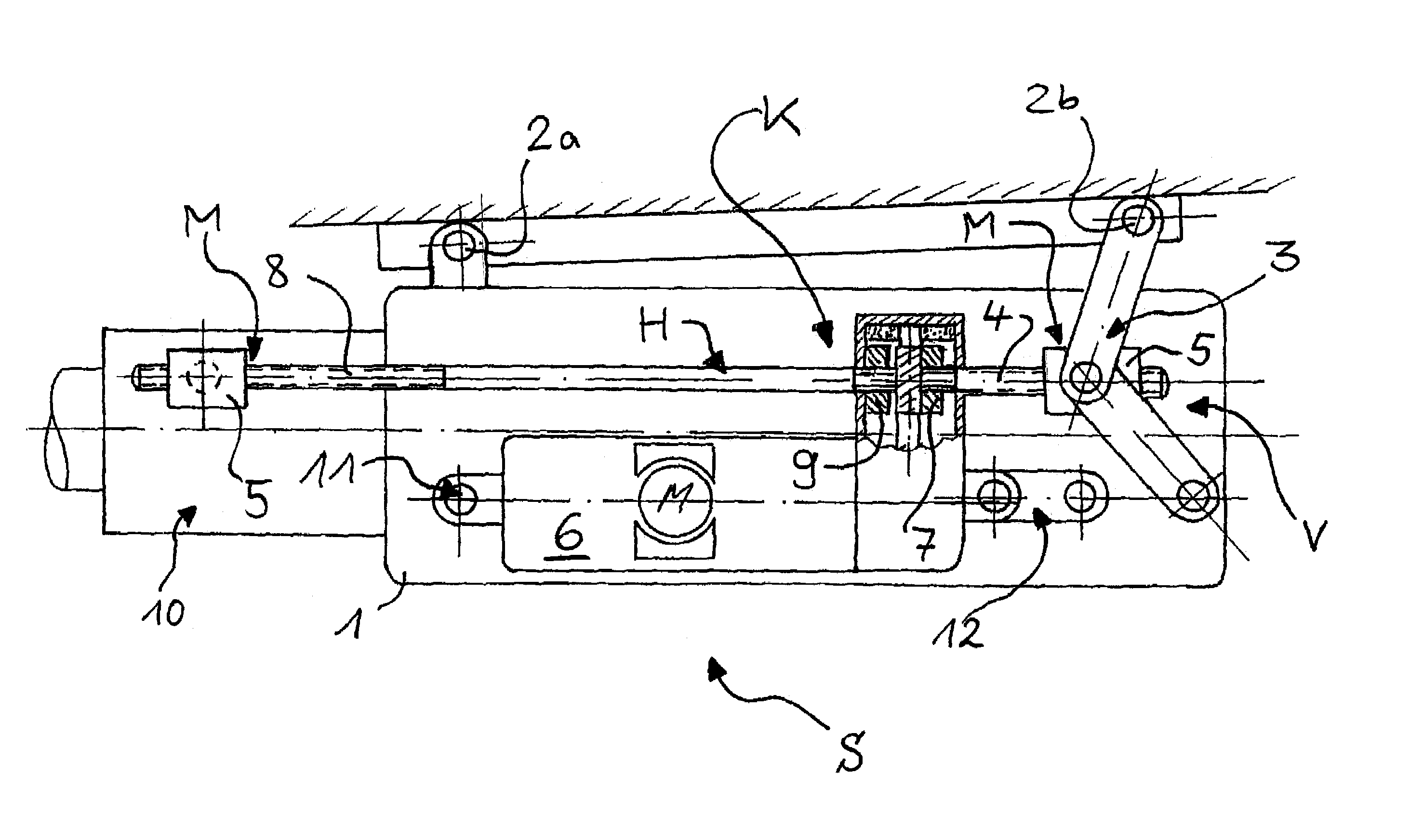
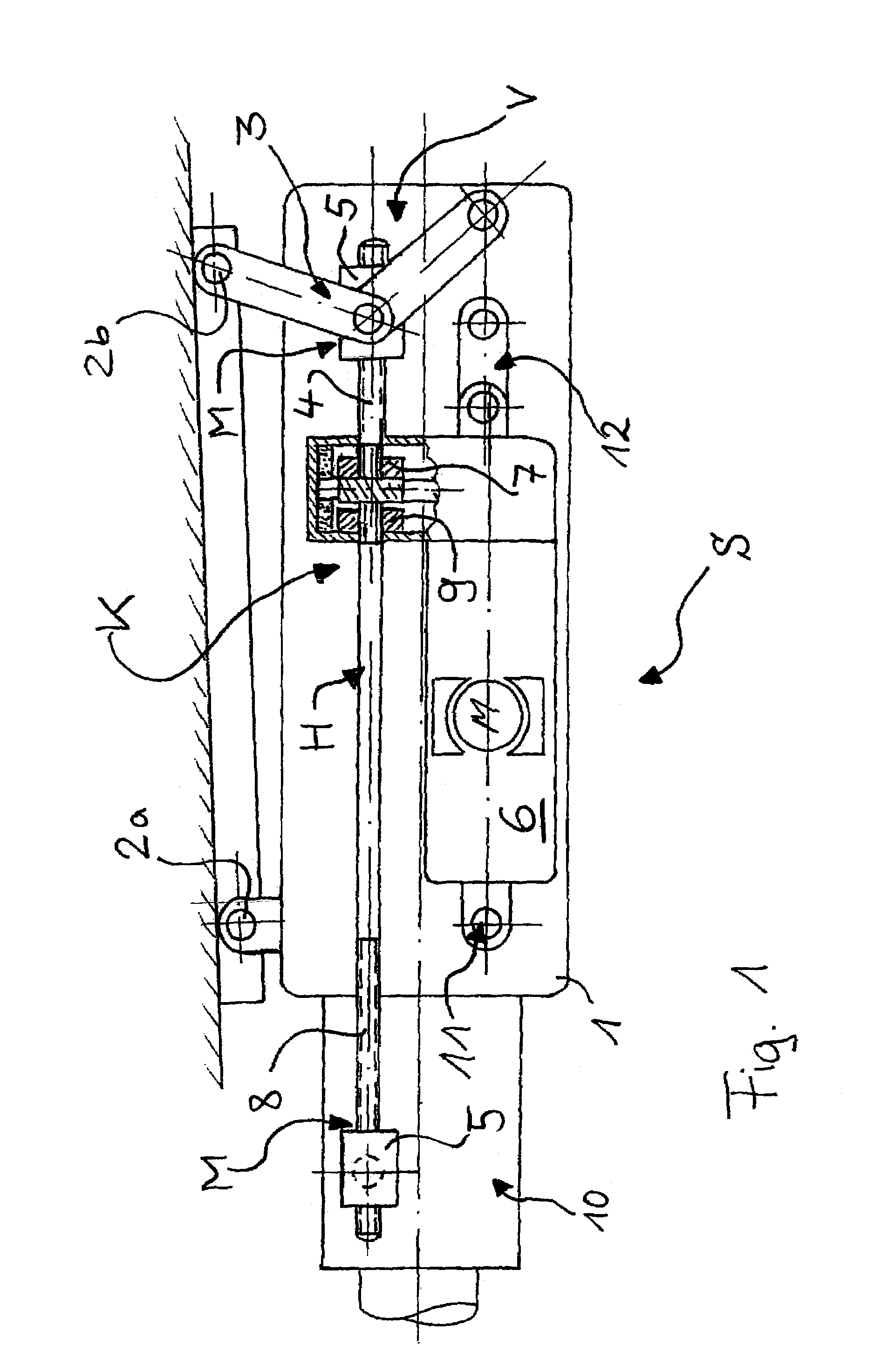
[0055]FIG. 1 shows a sectional cross section of the suspension of a safety steering mechanism S of steering mechanism housing 1 of steering column 10 on two suspension points 2a, 2b and two double levers or links as so-called articulated levers 3 that can be varied in length by “flexing.” Vertical adjustment threaded spindle 4 shortens articulated levers 3, which pivot apart or together in accordance with the direction of movement of vertical adjustment threaded spindle 4. Links 3 are pivotally fastened on nut 5. Steering housing 1 is pivoted up and down thereby. To this end, vertical adjustment threaded spindle 4 (up / down motion of steering column 10) is driven by adjustment motor 6 connected by vertical adjustment clutch 7 to vertical adjustment threaded spindle 4.

[0056]A longitudinal movement of steering column 10 in steering mechanism housing 1 is produced when switching motor 6 to longitudinal adjustment clutch 9 and therewith longitudinal adjustment threaded spindle 8 (back-an...

second embodiment

[0058]Alternatively, as can be seen in FIG. 2, cylinder 13 is built into longitudinal adjustment threaded spindle 8 (back-and-forth motion of steering column 10) in a second embodiment in accordance with the sectional cross section view of FIG. 2. Cylinder 13 is connected at one end to longitudinal adjustment coupling 9 and coupled on the opposite end to piston 14 on longitudinal adjustment threaded spindle 8. Piston 14 and cylinder 13 are suitably provided with teeth or splines 16 such that piston 14 entrains cylinder 13 rotationally, yet a longitudinal displacement is possible in a crash or in an accident situation.

[0059]In order to be able to absorb energy for the longitudinal displacement in a crash, a load absorption element is built into or, alternatively, around cylinder 13. Corrugated tube 15 is shown here in cylinder 13. Alternatively, other deforming materials are conceivable here or even a liquid that is pressed through a nozzle. In general, piston 14, cylinder 13 and cor...


PUM


Abstract

A safety steering mechanism for a steering column, with a steering-column comfort adjustment having linear positioning devices, and provided with safety devices designed such that, in an accident situation, at least an end area of the steering column can be moved away from a driver's position. The linear positioning devices include load absorption devices and / or withdrawal devices regarding the movement of at least the end area of the steering column away from a driver's position. An operating method for a safety steering mechanism for a steering column that can be adjusted by a comfort adjustment in accordance with the requirements and / or wishes of a driver by means of linear positioning devices and of which at least an end area of the steering column can be moved away from a driver's position in an accident situation. The movement of at least the end or the steering column away from a driver's position is braked in an accident situation in a load-receiving manner by load absorption devices contained in the linear positioning devices.

Description

BACKGROUND OF THE INVENTION[0001]1. Field of the Invention[0002]The invention relates to a safety steering mechanism and a method of operating[0003]The invention has embodiments and can be used in combination with steering mechanisms in accordance with international patent applications PCT / DE 99 / 01000, PCT / DE 01 / 00746, PCT / DE 01 / 00737, PCT / DE 00 / 01889 and PCT / DE 00 / 02286. In order to avoid mere repetitions, the disclosures of all these applications are completely included and incorporated herewith and herein by reference.[0004]2. Prior Art[0005]Numerous safety steering columns and operating methods for them are known for better protecting vehicle drivers in accidents. In this connection, safety steering mechanisms have become known in practice with a steering column, a steering-column comfort adjustment comprising linear positioning devices, and with safety devices designed such that that in an accident situation at least an end area of the steering column can be moved away from a d...

Claims


Application Information

Patent Timeline
Patent Type & Authority Patents(United States)
IPC IPC(8): B62D1/18B62D1/181B62D1/19
CPCB62D1/181B62D1/197B62D1/195
Inventor MULLER, OLAF
Owner THYSSENKRUPP PRESTA AG
Learn More