Cap with plastic sleeve

a technology of plastic sleeves and caps, applied in the field of caps with plastic sleeves, can solve the problems of not being able to develop commercially, significantly higher manufacturing costs, and not being able to meet the needs of customers,

Inactive Publication Date: 2001-10-16
PECHINEY EMBALLAGE ALIMENTAIRE
View PDF11 Cites 58 Cited by
  • Summary
  • Abstract
  • Description
  • Claims
  • Application Information

AI Technical Summary

Problems solved by technology

This solution to the problem has not been developed commercially because of the significantly higher cost of manufacture, bearing in mind the initial cost of the M / P / M type of multi-layer material, where M designates a metal layer of aluminum and P designates a layer of adhesive material.
The problem to be resolved is, on the one hand to provide caps which do not cut after being cut with a knife and which, at the same time, have a cost price which is not very high.

Method used


Image

  • Cap with plastic sleeve
  • Cap with plastic sleeve
  • Cap with plastic sleeve

Examples


embodiment examples

EXAMPLE 1

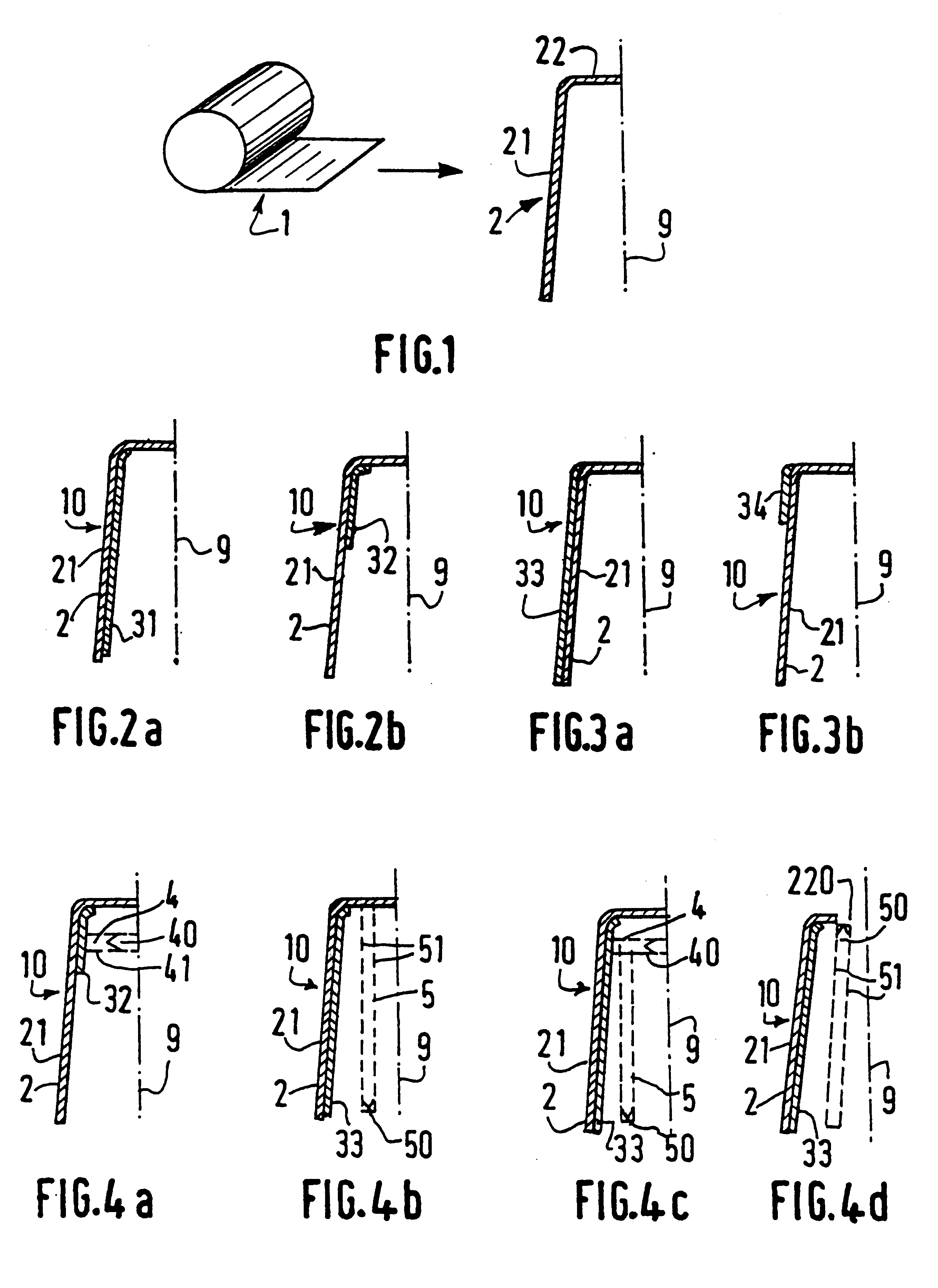
Blanks (2) were made in a 1000 series aluminum alloy conforming to FIG. 9 by stamping and drawing a strip of aluminum 100 .mu.m thick.

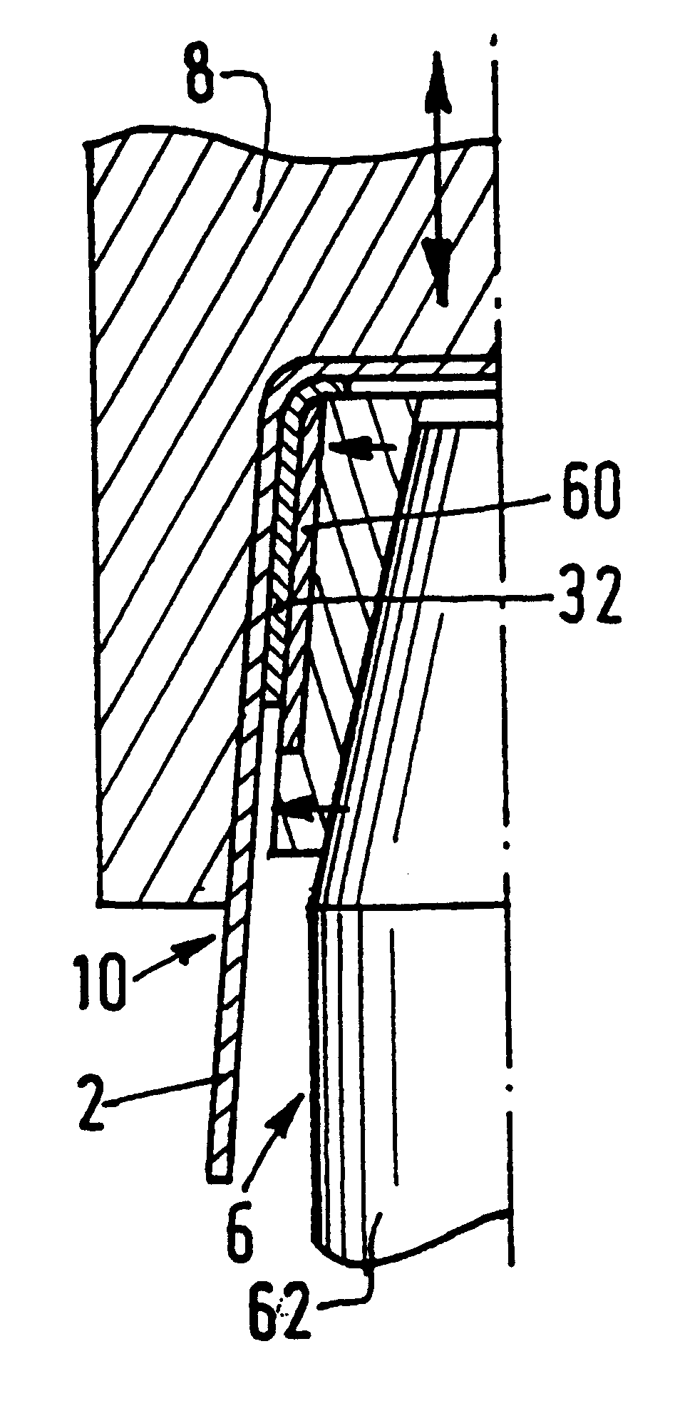
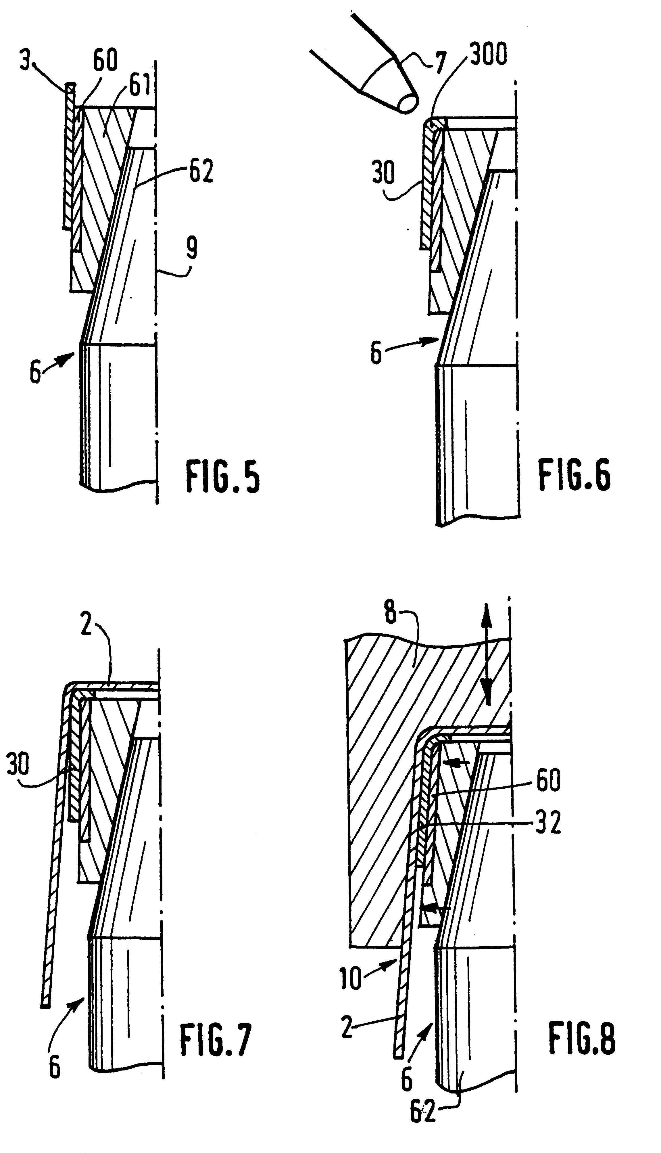
A roll of EAA / LDPE film, 29 mm diameter and 90 .mu.m thick, comprising a 30 .mu.m layer of EAA and a 60 .mu.m layer of LDPE formed by co-extrusion blow molding in a bubble. The device (13) described in FIG. 11 and in FIGS. 5 to 8 was used with regard to the detail of each step: At station 1, sleeves (30) were formed from the EAA / LDPE film, 28 mm in height having an overlap (300) of 4 mm provided instantaneously by blowing hot air (7). At station 2, the blanks (2) which had their final height, were supplied. At station 3, the heated die (8) was applied at a temperature of 240.degree. C. for 0.8 seconds and with an axial force of 300 daN converted into a radial force (200 daN) over a surface area of sleeve of about 1000 mm.sup.2 --being a pressure of about 0.18 daN / mm.sup.2. At station 4, the caps according to the invention were ejected. These ...

example 2

The caps according to the invention, identical to those of Example 1, were manufactured with additionally a tear strip (4) as shown in FIG. 10, since they were more specifically intended for the over-capping of bottles of spirits. This strip had a width of 6 mm.

Comparative Results

The caps from test 1 were compared to blank caps (2). The caps from test 2 were compared with capsules made of Softgard.RTM. tin fitted with a similar tear strip. The comparison of the caps was carried out by users in accordance with a specific protocol that included opening 15 bottles fitted with caps which were code named and in the presence of a person responsible for observing in detail all relevant facts.

The result of these tests was that the caps according to the invention were judged both with regard to their ease of opening and their safety of opening or their feel, superior to the reference caps for over-capping wine where the reference product was the blank cap itself, and comparable to the refere...


PUM

PropertyMeasurementUnit
thicknessaaaaaaaaaa
thicknessaaaaaaaaaa
Shore hardnessaaaaaaaaaa

Abstract

An overcap for a container including a head portion and a skirt portion, and a method for its production. The skirt portion has a metal wall and an opening area constructed and arranged to be broken during removal of the overcap. A sleeve of plastic material adheres to the metal wall over an area limited to the opening area.

Description

The invention relates to the field of caps, and more particularly to that of metal caps and over caps. Over caps, applied to the necks of containers fitted with a stopper, are intended, apart from their decorative effect, notably to guarantee that the containers are impregnable. These over caps are possibly fitted with means for easy first opening (score lines, detachable tabs, etc.. ), but if not, the head of the cap is cut off with a knife so that the container can then be opened.DESCRIPTION OF RELATED ARTNumerous metal over caps are already known, notably those described in the patents below, in the name of the applicant :in European Patent EP-B1-363 285, an over cap made of aluminum is described that is easily cut away and which has a peripheral ring or rib, so that a blade used to cut the cap when it is first opened is guided.in French patent FR-B1-2 636 257, a metal cap is described that has a non-cutting tear line provided by a succession of transverse reliefs and hollows.sim...

Claims


Application Information

Patent Timeline
Patent Type & Authority Patents(United States)
IPC IPC(8): B65D41/00B65D41/42B65D41/32B65D41/62
CPCB65D41/42B65D41/62Y10T29/49906
Inventor GRANGER, JACQUESPOYOL, RICHARD
Owner PECHINEY EMBALLAGE ALIMENTAIRE
Why Eureka
Try Eureka