Golf club head

a golf club and head technology, applied in the field of golf clubs, can solve the problems of increasing the stiffness of the club head, reducing the weight of the sole, and reducing the weight can have negative side effects

Inactive Publication Date: 2005-02-03
TAYLOR MADE GOLF
View PDF33 Cites 95 Cited by
  • Summary
  • Abstract
  • Description
  • Claims
  • Application Information

AI Technical Summary

Benefits of technology

[0013] The present invention provides a solution to counteract the negative side effects described above, by allowing club designers to design a club with an optimal center of gravity, while at the same time lowering the stiffness proximate the sole, creating more consistent flex while striking the ball, improving the feel of the club and reducing vibration.

Problems solved by technology

This results in a concentration of weight proximate the sole.
While it is recognized that the lower CG of the improved clubs can be beneficial, such a lowering can have negative side effects.
First, the concentrated mass proximate the sole can increase the stiffness of the club head.
This can cause a noticeable change in the club's feel.
Different sensations due to striking the ball in different locations on the club face may make a club less desirable to a potential user.
Second, the weight concentration proximate the sole can lead to different levels of flex at different points on the club face.
Such a change in flex can adversely affect performance.
Third, the weight concentration can lead to excess vibration, which can adversely affect the feel of the golf club, including the sound made by the club.

Method used


Image

  • Golf club head
  • Golf club head
  • Golf club head

Examples


Embodiment Construction

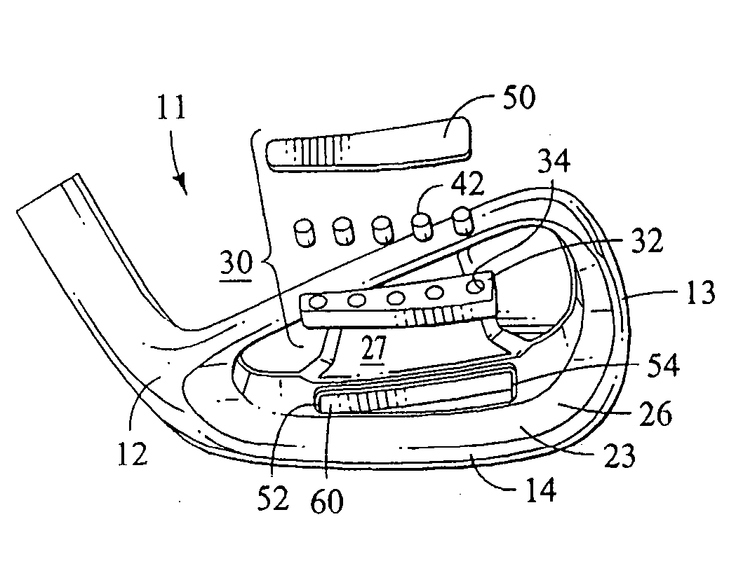
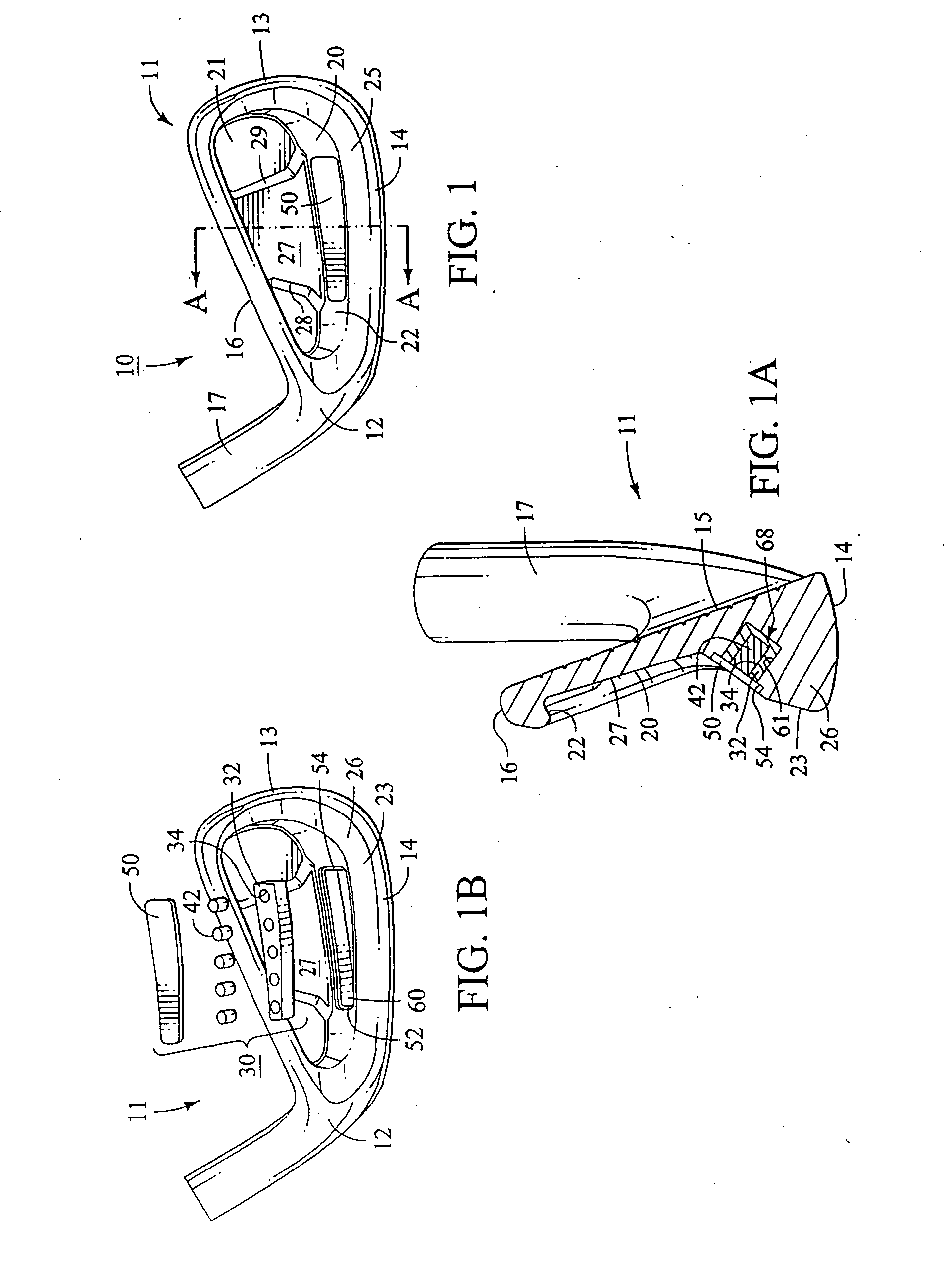
[0042] Referring now to a first embodiment of the present invention shown in FIGS. 1 and 1A, there is shown a golf club head 10 that is similar to many cavity back club heads that are known in the art. The club head 10 includes a body 11 having a heel 12, a toe 13, a sole 14, a front striking face 15, a top line 16, and a hosel 17. The body 11 also has a rear cavity 20 that has a cavity wall 21 that is substantially parallel to the striking face 15.

[0043] The cavity 20 includes a cavity rim 22 that extends substantially rearwardly from the cavity wall 21 proximate the heel 12, toe 13, sole 14 and top line 16, as shown in FIGS. 1 and 1A. The club head 10 has a perimeter weighting 25 that comprises a mass of material that extends rearwardly from the entirety or a portion of the perimeter of the club head proximate the cavity rim 22. The perimeter weighting 25 includes a sole bar 26 or mass concentration located proximate the sole 14 so as to provide the desired weight distribution ch...


PUM


Abstract

A golf club head is disclosed that comprises a body having a striking face, a rear cavity and a sole bar, wherein a recess is formed in the sole bar that extends generally from the rear cavity. An insert is located within the sole recess, the insert including a core and an intermediate layer that separates the core from the recess wall. The intermediate layer has a hardness and a modulus of elasticity that are less than that of the core, such that when the golf club head is used to strike a golf ball, the resulting vibrations are dissipated by compression of the intermediate layer and movement of the core with respect to the intermediate layer.

Description

CROSS-REFERENCE TO RELATED APPLICATION [0001] This is a continuation of application Ser. No. 10 / 234,663, filed Sep. 3, 2002, which is a continuation-in-part of application Ser. No. 09 / 728,955, filed Dec. 1, 2000 (now U.S. Pat. No. 6,592,468), both of which are herein incorporated by reference.BACKGROUND OF THE INVENTION [0002] The present invention relates generally to the golf clubs and, more particularly, to golf club heads. [0003] Modern golf clubs have typically been classified as either woods, irons or putters. The term “wood” is a historical term that is still commonly used, even for golf clubs that are constructed of steel, titanium, fiberglass or other more exotic materials, to name a few. The term “iron” is also a historical term that is still commonly used, even though those clubs are not typically constructed of iron, but are rather constructed of many of the same materials used to construct “woods”. [0004] Many advancements have been achieved, particularly over the past ...

Claims


Application Information

Patent Timeline
Patent Type & Authority Applications(United States)
IPC IPC(8): A63B53/04A63B59/00
CPCA63B53/047A63B53/0475A63B2053/0491A63B2053/0416A63B2053/0433A63B59/0092A63B60/02A63B60/54A63B53/0416A63B53/0433
Inventor WAHL, BRETBEACH, TODD P.VINCENT, BENOIT
Owner TAYLOR MADE GOLF
Why Eureka
Try Eureka