Vehicle steering apparatus

a steering apparatus and vehicle technology, applied in the direction of steering initiation, vessel construction, instruments, etc., can solve the problems of weakening the command control of the assistive electric motor, the control system is divergent, and the difficulty of always ensuring a desired assist, so as to reduce the influence of the dispersion among products and improve the steering feeling

Inactive Publication Date: 2006-04-27
NISSAN MOTOR CO LTD
View PDF6 Cites 106 Cited by
  • Summary
  • Abstract
  • Description
  • Claims
  • Application Information

AI Technical Summary

Benefits of technology

[0005] It is therefore an object of the present invention to provide a vehicle steering apparatus which is capable of achieving both of the improvement of the steering feeling and the decrease of the influence of the dispersion among products.

Problems solved by technology

However, this apparatus has a problem that it is difficult to always ensure a desired assist characteristic for reasons of a difficulty in firmly eliminating the influence of the dispersion among products although it is possible to suppress the dispersion due to electric motor or reduction gear.
However, if the feedback gain is increased, the assist control in the command to the electric motor is weaken.
If the feedback gain is simply set at a large value, there will be caused a possibility that the control system diverges.

Method used


Image

  • Vehicle steering apparatus
  • Vehicle steering apparatus
  • Vehicle steering apparatus

Examples


first embodiment

[0036] The first embodiment exemplifies an application of the vehicle steering apparatus of the present invention to an electric power-steering system.

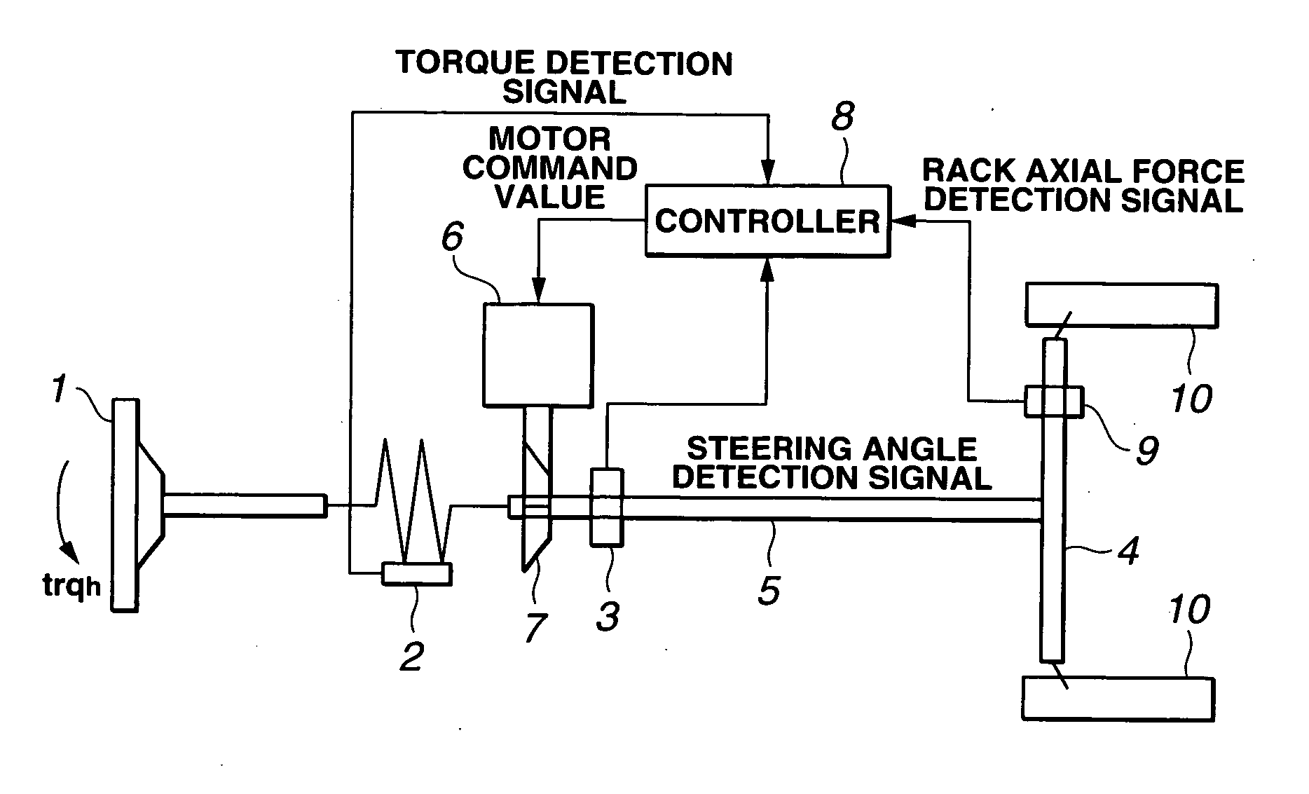
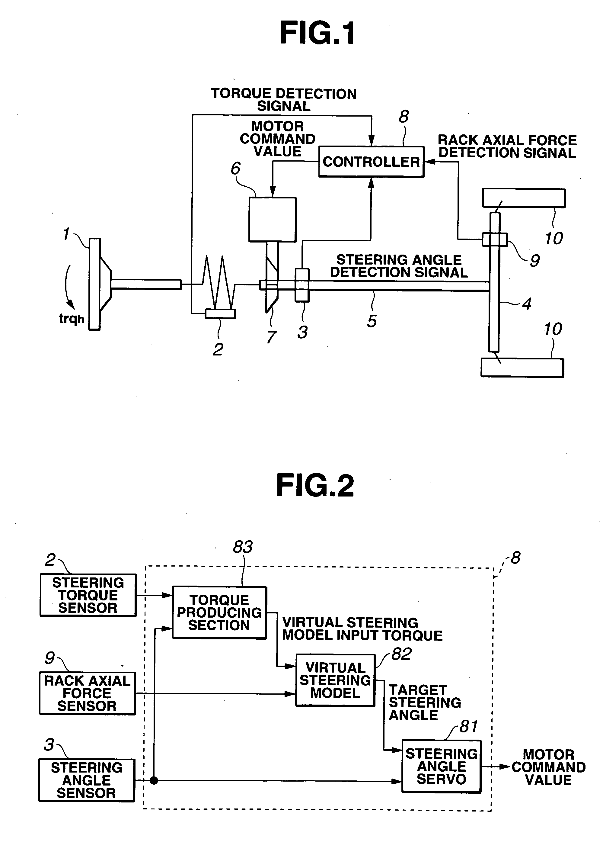
[0037]FIG. 1 is a schematic view showing the electric power steering system according to the first embodiment of the present invention. The electric power steering system comprises a steering wheel 1, a steering torque sensor 2, a steering angle sensor (turn angle sensor) 3, a steering rack (steering mechanism) 4, a column shaft (steering column shaft) 5, an assist motor (actuator) 6, a deduction gear 7, a controller 8, a rack axial force sensor 9, and steered wheels 10 and 10.

[0038] Steering torque sensor 2 is disposed on steering column shaft 5 between assist motor 6 and steering wheel 1. Steering torque sensor 2 detects a torsion of a torsion bar, which is produced by a driver's steering torque, and outputs the detected torsion to controller 8. Steering angle sensor 3 detects a turn angle (steering angle) of steering column shaft...

second embodiment

[0094] There is discussed the construction of the electric power steering system according to the second embodiment of the present invention.

[0095]FIG. 8 is a control block diagram showing the torque producing section of the second embodiment. The torque producing section 83′ of the second embodiment further includes a differentiator 83f and a multiplier 83g, in addition to the construction of the torque producing section of the first embodiment. Since the other constructions of the second embodiment are the same as those of the first embodiment, the parts as same as those of the first embodiment are denoted by the same reference numerals and the explanation thereof is omitted herein.

[0096] Differentiator 83f obtains a first-order differential of steering-wheel angle θh received from adder 83b as a steering-wheel angular speed θh′ and outputs it to multiplier 83g.

[0097] Multiplier 83g obtains the product θh′×D by multiplying the steering-wheel angular speed θh′ by an inverse valu...

third embodiment

[0103] A third embodiment shows a steer-by-wire system to which the vehicle steering apparatus of the present invention is applied.

[0104]FIG. 9 is a structural view showing the steer-by-wire system according to the third embodiment of the present invention. The steer-by-wire system comprises steering wheel 1, steering torque sensor 2, steering angle sensor (turn angle sensor) 3, rack (steering mechanism) 4, steering column shaft 5a, a pinion shaft 5b, a reaction force motor (actuator) 6′, a reduction gear 7, a controller 8′, steered wheels 10, a tire steering motor 11 and a reduction gear 12.

[0105] The steer-by-wire system of the third embodiment has a construction that steering column shaft 5 connected to steering wheel 1 is mechanically separated from pinion shaft 5b connected to steered wheels 10 and is arranged to steer the steered wheels 10 by controlling the tire steering motor 11 according to the steering angle and the steering torque. Herein, the explanation of a control o...


PUM


Abstract

A vehicle steering apparatus is comprised of an assist motor, a steering torque sensor, a steering angle sensor, and a controller. The controller has a torque producing section for estimating a virtual steering model input torque from a torque sensor detection value and a steering angle detection value, a virtual steering model of representing a desired steering characteristic which receives the virtual steering model input torque and outputs a target steering angle of a steering column shaft, and a steering angle servo for controlling an output of the assist motor so that the steering angle detection angle follows the target steering angle.

Description

BACKGROUND OF THE INVENTION [0001] The present invention relates to a vehicle steering apparatus which comprises an actuator for applying an axial torque to a steering column shaft. [0002] Japanese Published Patent Application No. 2003-81119 discloses an electric power-steering apparatus which is arranged to control an electric motor on the basis of a controlled variable which is a sum of a first controlled variable calculated from a steering torque detection value and a second controlled variable obtained based on a difference between a target motor turn angle calculated from the steering torque detection value and an actual motor turn angle, with intent to achieve both of ensuring a desired assist characteristic and an improvement of a steering feeling. This electric power-steering system is arranged such that the steering torque value includes a predetermined friction component, with intent to further improve the steering feeling by remaining a predetermined hysteresis characteri...

Claims


Application Information

Patent Timeline
Patent Type & Authority Applications(United States)
IPC IPC(8): B62D5/04
CPCB62D5/0463B62D6/003B62D6/008
Inventor FURUSHO, HIROYUKINAWANO, MASAAKI
Owner NISSAN MOTOR CO LTD
Why Eureka
Try Eureka