AI technical title is built by Patsnap AI team. It summarizes the technical point description of the patent document.
a technology of electrophoretic displays and gaseous fluids, applied in the direction of instruments, static indicating devices, etc., can solve the problems of gas-based electrophoretic media being susceptible to the same types of problems, widespread use, and inadequate service life of these displays, so as to reduce the effect of prior history
Inactive Publication Date: 2008-01-31
E INK CORPORATION
View PDF99 Cites 387 Cited by
Summary
Abstract
Description
Claims
Application Information
AI Technical Summary
This helps you quickly interpret patents by identifying the three key elements:
Problems solved by technology
Method used
Benefits of technology
Benefits of technology
[0056]Since the impulse applied to the display in the increasing impulse display and method of the present invention is the integral of the applied voltage with respect to time, increase of this impulse may be effected in various ways. For example, the maximum voltage applied to the display may be increased with increasing time since the reference time (i.e., increasing determined period). Alternatively, the average voltage applied to the display may be increased with increasing time since the reference time. Another possibility, which may be employed with drivers which are only capable of applying one or a limited number of voltages of a given polarity to the display, is to increase the length of the drive pulse with increasing time since the reference time.
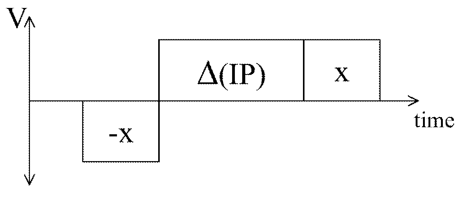
[0075]In the AC pulse display and method of the present invention, the AC pulse or pulses may be accompanied by one or more DC pulses to effect a desired transition between optical states of the relevant pixel of the display. The AC and DC pulses may be arranged in any order, and there may be multiple pulses of both types. However, it may be advantageous for the AC pulses to be applied at the beginning of the waveform used for the transition, since the AC pulses tend to restore the electrophoretic particles to a relatively standard state and reduce the effects of the prior history of the particles.
Problems solved by technology
Nevertheless, problems with the long-term image quality of electrophoretic displays have prevented their widespread usage.
For example, particles that make up electrophoretic displays tend to settle, resulting in inadequate service-life for these displays.
Such gas-based electrophoretic media appear to be susceptible to the same types of problems due to particle settling as liquid-based electrophoretic media, when the media are used in an orientation which permits such settling, for example in a sign where the medium is disposed in a vertical plane.
Indeed, particle settling appears to be a more serious problem in gas-based electrophoretic media than in liquid-based ones, since the lower viscosity of gaseous suspending fluids as compared with liquid ones allows more rapid settling of the electrophoretic particles.
Method used
Image
Click on the blue label to locate the original text in one second.
Reading with bidirectional positioning of images and text.
Examples
Embodiment Construction
[0086]As will be apparent from the preceding discussion, the present invention relates to gas-based electrophoretic displays, and methods for driving such displays, in which the drive impulse or the length or amplitude of AC pulses, of the waveform used for a specific transition, is increased to compensate for various time dependent effects, including aging of the display and the dwell time since the display, or a specific pixel thereof, has been rewritten, or the number of times the display or pixel has been rewritten. Although the increased impulse, increasing switch count and AC pulse displays and methods of the present invention have been described separately above, it will be appreciated that, in practice, a single display might make use of multiple aspects of the present invention; for example, an increased impulse method could be used to compensate for aging of the display and the AC pulse method to compensate for dwell time effects. Alternatively or in addition, one or more ...
PUM
Abstract
An electrophoretic display comprises a pair of facing substrates, at least one of which is transparent, a plurality of particles and a gas between the substrates, and means for applying an electric field to cause the particles to move and thus change the electro-optic state of the display. The electric field means is arranged to increase the impulse applied to the display with increasing time since a reference time, or with increasing number of images written on the display. In another embodiment, an alternating current pulse is applied to the display, and the duration and / or amplitude of the alternating current pulse is increased with increasing time since a reference time.
Description
REFERENCE TO RELATED APPLICATIONS[0001]This application claims benefit of copending Application Ser. No. 60 / 820,235, filed Jul. 25, 2006.[0002]This application is related to a series of patents and applications assigned to E Ink Corporation, this series of patents and applications being directed to MEthods for Driving Electro-Optic Displays, and hereinafter collectively referred to as the “MEDEOD” applications. This series of patents and applications comprises:[0003](a) U.S. Pat. No. 6,504,524;[0004](b) U.S. Pat. No. 6,531,997;[0005](c) U.S. Pat. No. 7,012,600;[0006](d) copending application Ser. No. 11 / 160,455, filed Jun. 24, 2005 (Publication No. 2005 / 0219184;[0007](e) copending application Ser. No. 11 / 307,886, filed Feb. 27, 2006 (Publication No. 2006 / 0139310);[0008](f) copending application Ser. No. 11 / 307,887, filed Feb. 27, 2006 (Publication No. 2006 / 0139311);[0009](g) U.S. Pat. No. 7,193,625;[0010](h) copending application Ser. No. 11 / 611,324, filed Dec. 15, 2006 (Publication...
Claims
Application Information
Patent Timeline
Application Date:The date an application was filed.
Publication Date:The date a patent or application was officially published.
First Publication Date:The earliest publication date of a patent with the same application number.
Issue Date:Publication date of the patent grant document.
PCT Entry Date:The Entry date of PCT National Phase.
Estimated Expiry Date:The statutory expiry date of a patent right according to the Patent Law, and it is the longest term of protection that the patent right can achieve without the termination of the patent right due to other reasons(Term extension factor has been taken into account ).
Invalid Date:Actual expiry date is based on effective date or publication date of legal transaction data of invalid patent.
Patent Type & AuthorityApplications(United States)

