Method for avoiding interference

a technology of interference prevention and interference prevention, applied in the field of radio communication, can solve the problems of inability to perform a communication with the bs, inability to perform a communication with the ms, and inability to perform a communication with an inferior communication quality, so as to reduce the influence of interference, reduce interference, and reduce interferen

Active Publication Date: 2011-12-22
LG ELECTRONICS INC
View PDF2 Cites 160 Cited by
  • Summary
  • Abstract
  • Description
  • Claims
  • Application Information

AI Technical Summary

Benefits of technology

[0042]To achieve these and other advantages and in accordance with the purpose of the present invention, as embodied and broadly described herein, there is still also provided a method for avoiding interference, the method comprising: transmitting a reference signal by a first base station; receiving, by the first base station, feedback information measured by an adjacent second base station with respect to the reference signal; controlling, by the first base station, transmission power of data transmitted / received between the first base station and a relay station placed within the coverage of the first base station, into a level not causing interference with radio resource of the second base station, based on the feed back information; and transmitting, by the first base station, the data to the relay station placed within the coverage of the first base station with the controlled transmission power.
[0043]The present invention may reduce interference occurring when signals are exchanged among the base station, the relay station and the terminals.
[0044]Especially, in the present invention, the base station may transmit backhaul data to the relay station with using UL resources due to deficient DL resources, etc. This may reduce the influence of interference on the adjacent base station.
[0045]Furthermore, in the present invention, the relay station may transmit backhaul data to the base station with using DL resources due to deficient UL resources, etc. This may reduce the influence of interference on the adjacent base station.

Problems solved by technology

Therefore, a downlink transmission by a base station (BS) and an uplink transmission by a mobile station (MS) cannot be simultaneously performed.
However, when there is an obstacle such as a building or when the terminal or the MS is positioned at a cell boundary, the MS cannot perform a communication with the BS or can perform a communication with an inferior communication quality.

Method used


Image

  • Method for avoiding interference
  • Method for avoiding interference
  • Method for avoiding interference

Examples


first embodiment

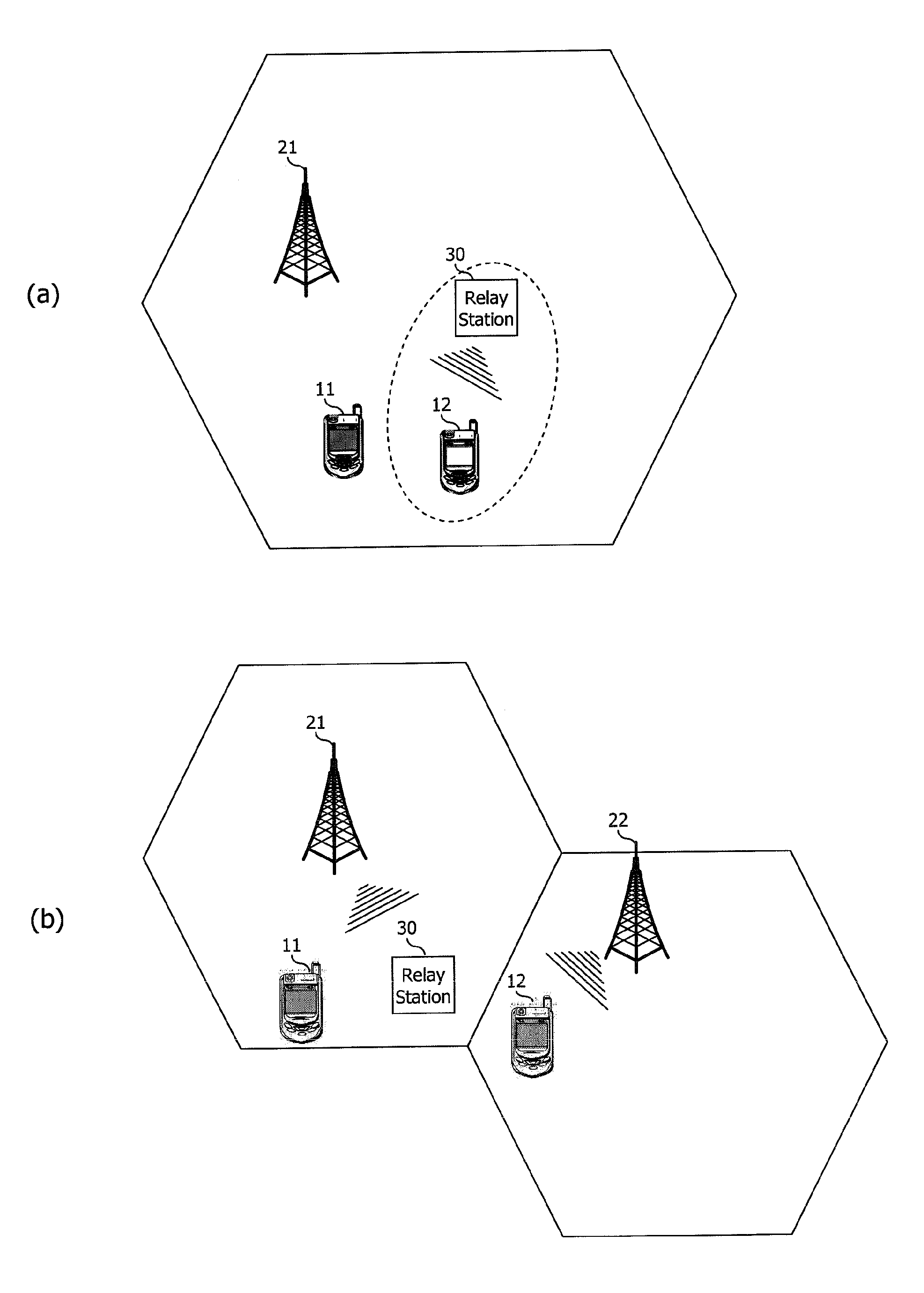
[0063]FIG. 5 is an exemplary view illustrating the present invention.

[0064]As can be seen from FIG. 5, a first base station 210 and a second base station 220 are adjacent to each other. A first relay station 310 is positioned at an outer periphery of the coverage of the first base station 210. And, a first terminal 110 is placed within the coverage of the first base station 210, and a second terminal 120 is placed within the coverage of the second base station 220. The first base station 210 and the second base station 220 are controlled by a control station 500 (e.g., RNC or SGSN of UTRAN, or MME (Mobility Management Entity) or Serving-GW of EPC (Evolved Packet Core), or IEEE 802.16dml ASN-GW or CSN).

[0065]An entity in the first base station 210 schedules UL radio resources and DL radio resources. Alternatively, the control station 500 schedules UL radio resources and DL radio resources of the first base station 210.

[0066]The first base station 210 transmits, to the first relay sta...

second embodiment

[0072]FIG. 6 is an exemplary view of the present invention.

[0073]As can be seen from FIG. 6, a first base station 210 and a second base station 220 are adjacent to each other. A first relay station 310 is positioned at an outer periphery of the coverage of the first base station 210. And, a first terminal 110 is placed within the coverage of the first base station 210, and a second terminal 120 is placed within the coverage of the second base station 220.

[0074]The first base station 210 schedules UL radio resources and DL radio resources.

[0075]A method for scheduling radio resources of the first relay station 310 includes a center-concentrated scheduling method and a distribution-type scheduling method. According to the center-concentrated scheduling method, the first base station 210 directly allocates radio resources of the first relay station. On the other hand, according to the distribution-type scheduling method, the first base station 210 schedules radio resources to the first...

fourth embodiment

[0101]FIG. 9 is an exemplary view of the present invention.

[0102]Referring to FIG. 9, in a similar manner to FIG. 8, the first relay station 310 may transmit backhaul data to the first base station 210 in some cases (e.g., when UL resources are deficient). Data transmission by the relay station with using DL resources may be referred to as DL band stealing or DL subframe stealing.

[0103]In this case, a transmission signal of the first relay station 310 may cause interference with DL transmission to the second terminal 120 by the adjacent second base station 220.

[0104]In order to solve the interference, in the fourth embodiment, the second base station 220 identifies the DL resources through which the backhaul data is transmitted, in a similar manner to the third embodiment. And, the second base station 220 schedules its DL resources, based on the identified DL resources. For instance, the second base station 220 may not allocate its radio resources corresponding to a time point when ...


PUM


Abstract

The present invention provides a method for avoiding interference resulting from data transmission between an adjacent second base station and a second relay station placed within the coverage of the adjacent second base station. The method for avoiding interference comprises: receiving the radio resource scheduling information from the adjacent second base station; checking the radio resources used in the data transmission between the adjacent second base station and the second relay station based on the received radio resource scheduling information; and scheduling at least one radio resource among uplink radio resources and downlink radio resources for at least one first terminal and at least one first relay station which are connected to a first base station in order to avoid interference with the checked radio resource if the radio resource used in the data transmission from the second base station to the second relay station is checked as the uplink resource or if the radio resource used in the data transmission from the second relay station to the second base station is checked as the downlink resource.

Description

TECHNICAL FIELD[0001]The present invention relates to radio communications, and more particularly, to a method for avoiding interference due to the addition of a relay station in a radio communications system.Background Art[0002]A radio communications system may be largely categorized into an FDD (Frequency Division Duplex) scheme and a TDD (Time Division Duplex) scheme.[0003]According to the FDD scheme, an uplink transmission and a downlink transmission are performed through different frequency bands. According to the TDD scheme, an uplink transmission and a downlink transmission are performed through the same frequency band and at different times. According to the TDD scheme, channel responses are substantially reciprocal to each other. This means that a downlink channel response and an uplink channel response are almost the same in a given frequency region. Accordingly, in a TDD-based radio communications system, a downlink channel response can be acquired from an uplink channel ...

Claims


Application Information

Patent Timeline
Patent Type & Authority Applications(United States)
IPC IPC(8): H04W24/00H04B7/005
CPCH04B7/2606H04W84/047H04W72/082H04W72/0426H04W72/27H04W72/541
Inventor SEO, HAN-BYULKIM, BYOUNG-HOON
Owner LG ELECTRONICS INC
Why Eureka
Try Eureka