Coil configurations for inductive power transer

a technology of inductive power transer and coil configuration, which is applied in the direction of transformers, inductances, safety/protection circuits, etc., can solve the problem that the resonance circuit cannot be selected, and achieve the effect of improving power transfer efficiency, power transfer efficiency, and power transfer efficiency

Active Publication Date: 2011-12-15
PHILIPS IP VENTURES BV
View PDF2 Cites 404 Cited by
  • Summary
  • Abstract
  • Description
  • Claims
  • Application Information

AI Technical Summary

Benefits of technology

[0014]In another aspect, the present invention may provide a method for tuning the wireless power system including the general steps of measuring an operating characteristic in the primary unit, measuring an operating characteristic in the receiver unit and tuning one or more of the components in the primary unit and the secondary unit based on a comparison of the two measurements. The method for tuning may be used with respect to the primary coil and the secondary coils to determine an understanding of the appropriate settings for inductive coupling between the primary unit and the secondary unit. For example, the wireless power system may compare the two measurements and tune the primary unit and/or receiver unit to improve power transfer efficiency. Based upon the comparison, the wireless power system may determine (1) if the resonant frequency of the primary unit may be tuned differently and (2) if the resonant frequency or frequencies of the receiver unit may be tuned differently to improve power transfer efficiency.
[0015]In one embodiment, a method for operating the wireless power system includes sweeping the drive frequency of the primary unit to build a frequency response table. The frequency response table may include measured

Problems solved by technology

Moreover, if the proximity of the receiving unit is such that the affect on mutu

Method used


Image

  • Coil configurations for inductive power transer
  • Coil configurations for inductive power transer
  • Coil configurations for inductive power transer

Examples


Embodiment Construction

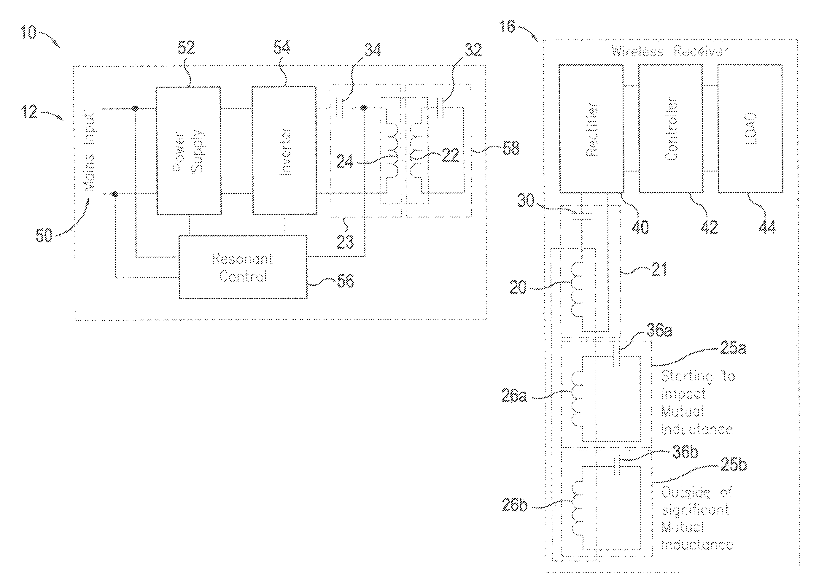
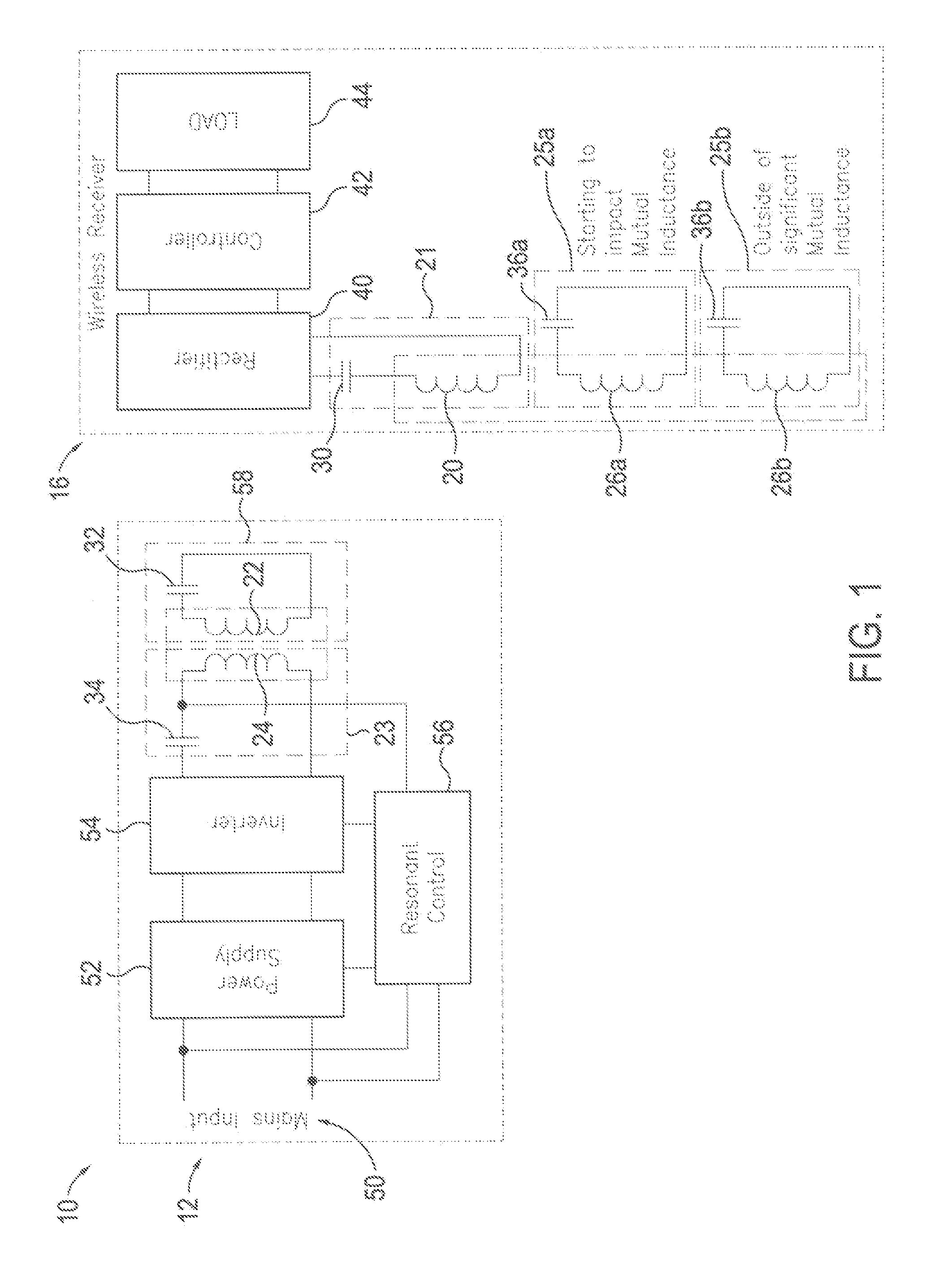
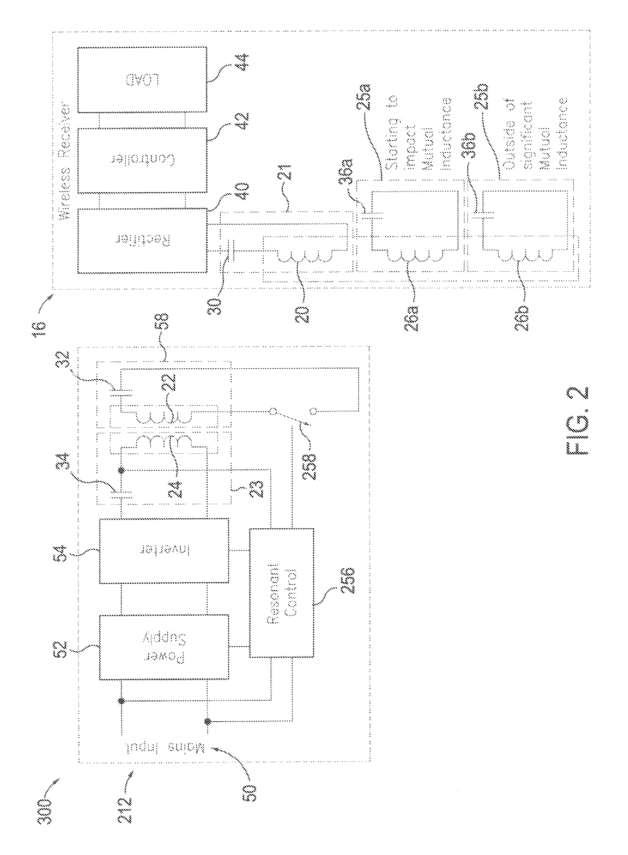
[0038]A wireless power supply system 10 in accordance with an embodiment of the present invention is shown in FIG. 1. The wireless power supply system 10 includes a primary unit 12 that transmits power using an electromagnetic field and a portable device having a receiver unit 16 for receiving the power transmitted via the electromagnetic field. The portable device is separate from and readily movable with respect to the primary unit 12. The receiver unit 16 includes a secondary tank circuit 21 and a plurality of resonating circuits 25a-b. The secondary tank circuit 21 and the plurality of resonating circuits 25a-b may each be configured differently to provide improved power transfer efficiency when the portable device is at different locations with respect to the primary unit 12. Configuration may be achieved using any number of approaches that change circuit impedance. The number of different receiver unit 16 resonating circuits 25a-b may vary from application to application depen...


PUM


Abstract

An inductive power supply system in which the receiving unit includes a secondary coil and a plurality of resonating circuits with different characteristics. Each of the resonating circuits may include a resonating coil and a resonating capacitor. The resonating coils may be inductively coupled to the secondary coil so that energy may be transferred from one or more of the resonating coils to said receiving unit. The plurality of resonating circuits are configured to provide improved power transfer efficiency or performance at different distances between the primary coil and secondary coil. The present invention may also provide a method for tuning the wireless power system including the general steps of measuring an operating characteristic in the primary unit, measuring an operating characteristic in the receiver unit and tuning one or more of the components in the primary unit and the secondary unit based on a comparison of the two measurements.

Description

FIELD OF THE INVENTION[0001]The present invention relates to wireless power supply systems, and more particularly to coil configurations for wireless power supply systems.BACKGROUND OF THE INVENTION[0002]Inductive power supply systems allow power to be transferred to an electronic device, such as a portable device, without the need for direct electrical connections. Inductive power transfer may be achieved using inductors, which produce magnetic fields when current flows through them. Conversely, current may be induced in an inductor when in the presence of a magnetic field, such as the magnetic field produced by another inductor. If two inductors are placed in proximity and one inductor is driven with a current, then the other inductor will produce a current even though the two inductors are not directly connected. This interrelationship between the two inductors is generally called inductive coupling, and many have used this phenomenon to transfer power without electrical connecti...

Claims


Application Information

Patent Timeline
IPC IPC(8): H01F38/00
CPCH02J17/00H02J5/005H02J50/12H02J50/402H02J7/00308H02J7/00304H02J50/80H02J50/90H02J50/40H02J7/0029H04B5/0037H04B5/0075
Inventor BAARMAN, DAVID W.
Owner PHILIPS IP VENTURES BV
Why Eureka
Try Eureka