Dual-transformer type of dc-to-dc converter

a converter and converter technology, applied in the direction of dc-dc conversion, power conversion systems, instruments, etc., can solve the problems of increasing the need to use a plurality of expensive types of switching elements with a high breakdown voltage level, and the increase of the manufacturing cost of dc-to-dc converters. to achieve the effect of increasing the efficiency of power transfer

Active Publication Date: 2008-04-10
DENSO CORP +1
View PDF12 Cites 33 Cited by
  • Summary
  • Abstract
  • Description
  • Claims
  • Application Information

AI Technical Summary

Benefits of technology

[0011] It is a purpose of the present invention to overcome the above problems, by providing a dual-transformer DC-to-DC converter in which requirements for the breakdown voltage level of switching elements in the converter can be substantially reduced by comparison with the prior art, and whereby increased efficiency of power transfer can be achieved.

Problems solved by technology

This is especially valuable in the case of an apparatus that is to be installed in a vehicle, since the available space for installing equipment is limited.
However with the DC-to-DC converters of reference documents 3 and 4, since high voltages are applied across the terminals of the switching elements in the high-voltage side of the apparatus, there is the disadvantage that it is necessary to use a plurality of expensive types of switching elements having a high breakdown voltage level.
Hence, a switching element having a high breakdown voltage level has a high level of switching loss.
Hence the manufacturing cost of the DC-to-DC converter becomes increased.

Method used


Image

  • Dual-transformer type of dc-to-dc converter
  • Dual-transformer type of dc-to-dc converter
  • Dual-transformer type of dc-to-dc converter

Examples


modification 1

Modification 1

[0125] The embodiment can be modified to make the duty ratio D change only gradually, after the apparatus is switched on. This will serve to prevent an excessive level of surge current flow into the smoothing capacitors.

modification 2

Modification 2

[0126] The embodiment has been described for the case of performing voltage step-down DC-to-DC conversion. However the embodiment could be modified to perform voltage step-up, by appropriately changing the ratio of numbers of turns of the primary and secondary windings of the transformer pair T1, T2.

modification 3

Modification 3

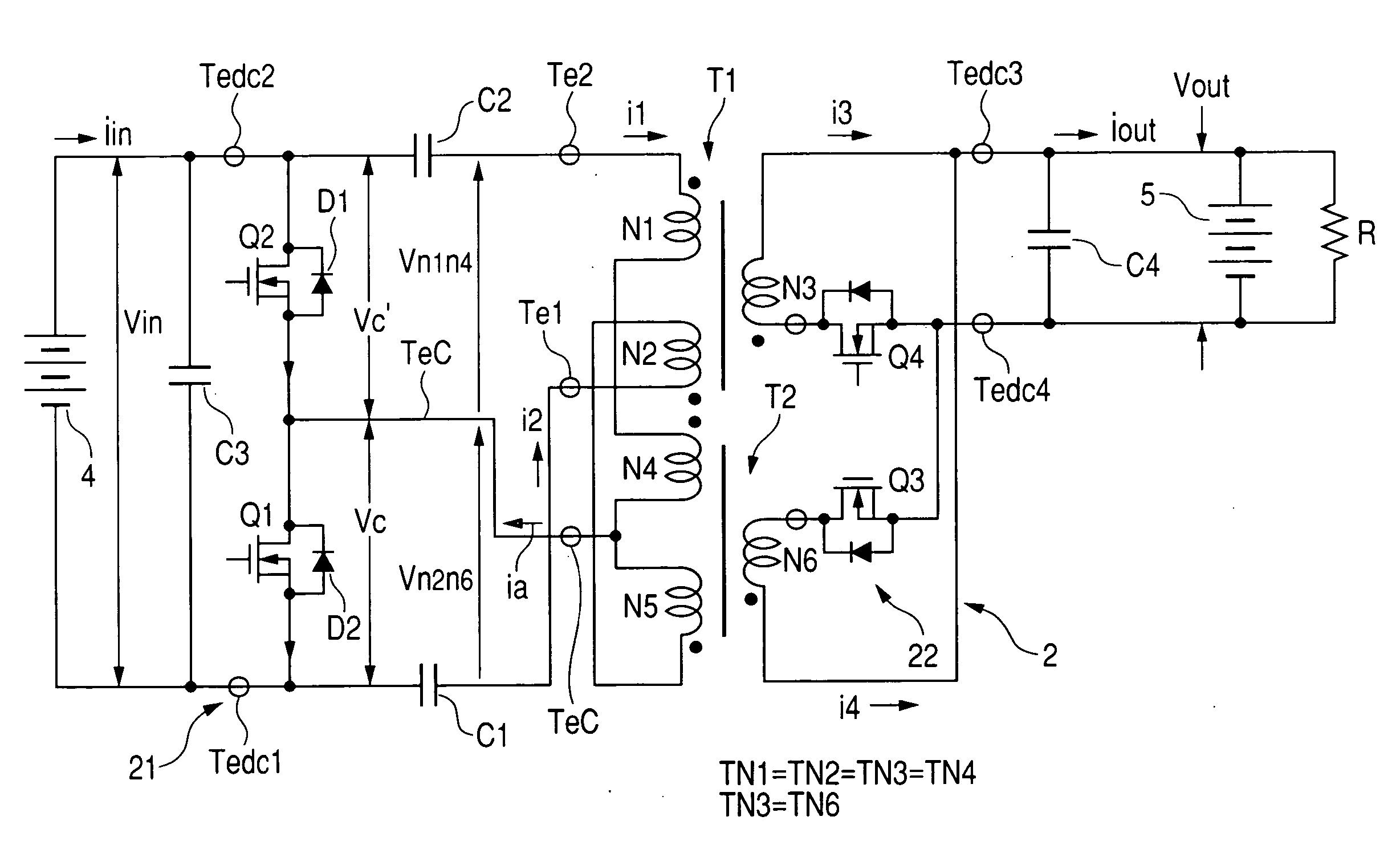
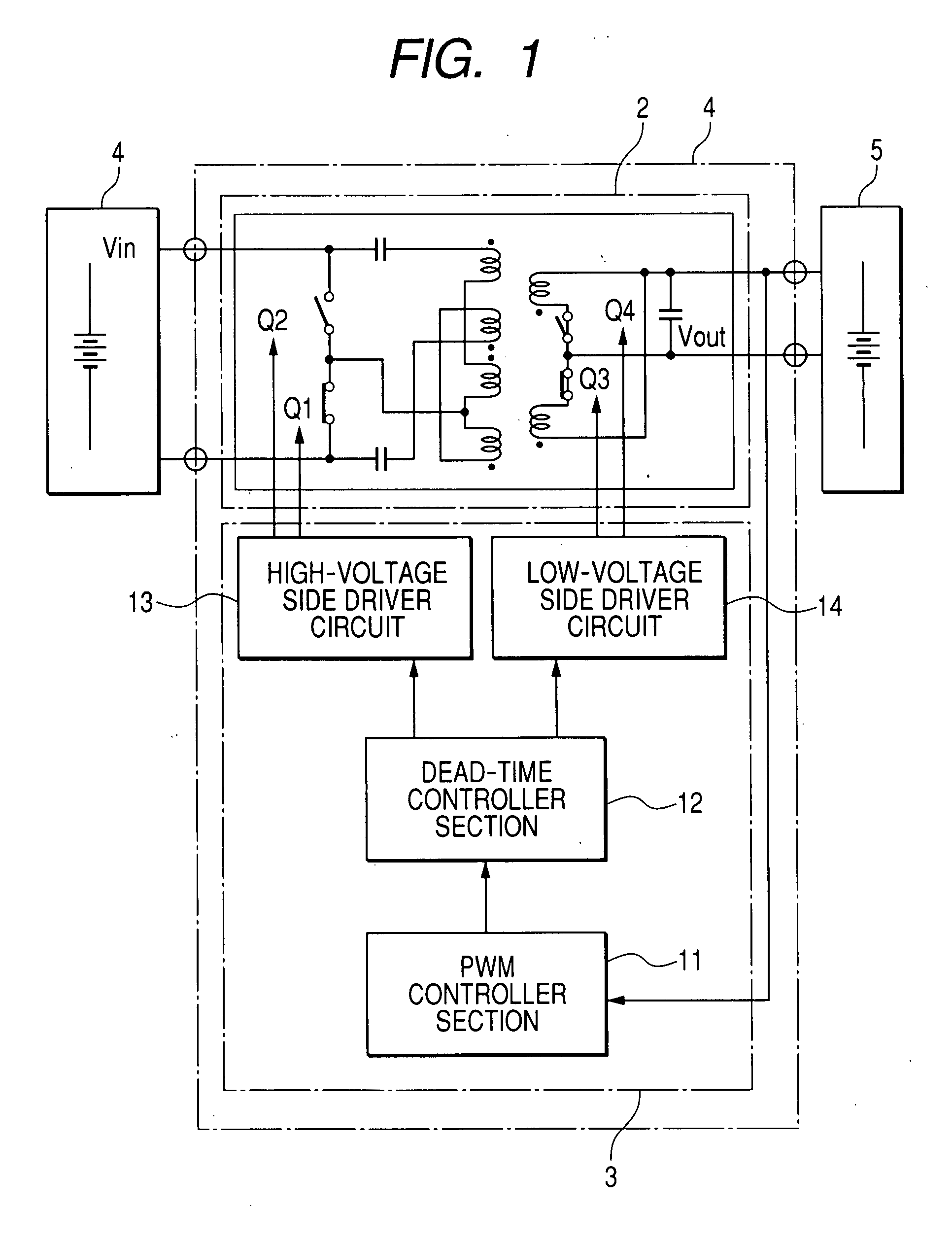
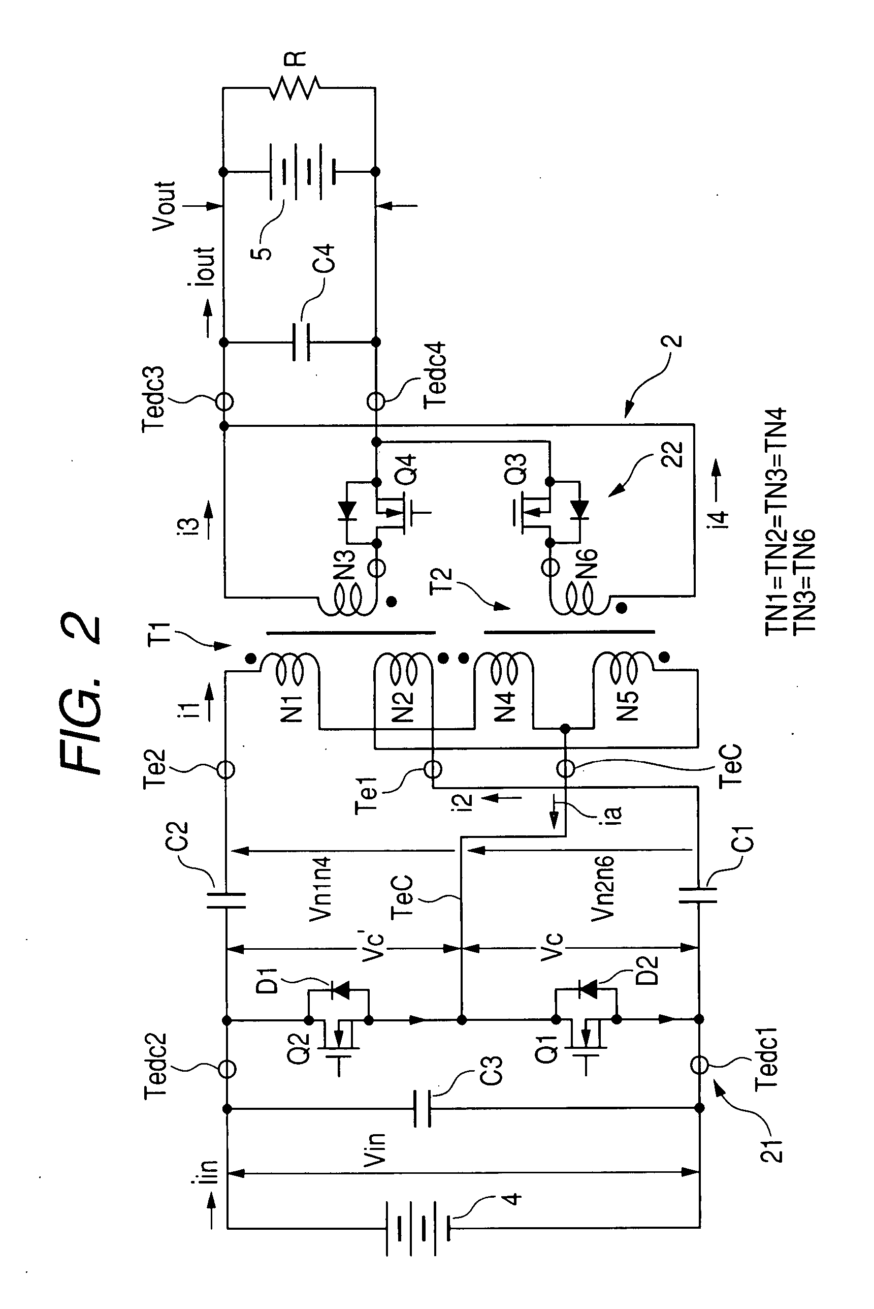
[0127] The embodiment has been described for the case of the switching elements Q3 and Q4 performing synchronous rectification, by performing complementary on / off switching that is synchronized with the complementary on / off switching of the switching elements Q1, Q2. However if only unidirectional DC-to-DC conversion from the high-voltage power source 4 to the low-voltage power source 5 is to be performed, one or both of the switching elements Q3 and Q4 could be replaced by rectifier diodes.


PUM


Abstract

A first AC/DC converter circuit is coupled via two transformers to a second AC/DC converter circuit, the first AC/DC converter circuit having a symmetrical configuration of two switching elements performing complementary opened/closed switching, to alternately connect positive and negative terminals of a DC source to a junction between transformer primary windings. Each primary winding alternates between a condition of transferring electrical power to a secondary winding and a condition of serving as a choke coil which temporarily stores electromagnetic energy when a current flows through that primary winding and a primary winding of the other transformer.

Description

CROSS-REFERENCE TO RELATED APPLICATIONS [0001] This application is based on and incorporates herein by reference Japanese Patent Application No. 2006-273204 filed on Oct. 4, 2006. BACKGROUND OF THE INVENTION [0002] 1. Field of Application [0003] The present invention relates to a dual-transformer type of DC-to-DC converter, and in particular to an improved DC-to-DC converter providing high efficiency of conversion. [0004] 2. Description of Prior Art [0005] Types of DC-to-DC converter which utilize two transformers have been proposed in the prior art, for example in Japanese patent application first publication No. 2003-102175 (referred to in the following as reference document 1), U.S. Pat. No. 5,291,382 (referred to in the following as reference document 2), Japanese patent application first publication No. 2005-51994 (referred to in the following as reference document 3), and Japanese patent application first publication No. 2005-51995 (referred to in the following as reference do...

Claims


Application Information

Patent Timeline
Patent Type & Authority Applications(United States)
IPC IPC(8): H02M3/335
CPCH02M3/33576
Inventor KAWASAKI, KOJIYAMASHITA, TSUYOSHI
Owner DENSO CORP
Why Eureka
Try Eureka