Electric vehicle

a technology of electric vehicles and coupling strength, applied in the direction of secondary cell servicing/maintenance, capacitor propulsion, rail devices, etc., can solve the problems of high critical circuit and installation design (subjected to large limitations), and achieve the effect of high electric power transmission efficiency, and increasing coupling strength k

Inactive Publication Date: 2012-12-20
HONDA MOTOR CO LTD
View PDF4 Cites 33 Cited by
  • Summary
  • Abstract
  • Description
  • Claims
  • Application Information

AI Technical Summary

Benefits of technology

[0014]According to the present invention, the index Q concerning energy retained between the electric transmitting coil underneath the road surface and the second coil of the relay, which forms the second wireless coupling in coaction with the electric transmitting coil, is increased, and the first coil of the relay and the electric receiving coil are disposed in close proximity to each other. Therefore, the coupling strength k is increased. Consequently, the figure of merit k·Q of the path from the electric transmitting coil underneath the road surface to the electric receiving coil of the electric vehicle 10 can also be increased. As a result, even if the electric vehicle and the road surface are distant from each other, the electric storage device can be charged with high electric power transmission efficiency through the relay.
[0015]The electric receiving coil and the first coil may be aligned coaxially with each other for thereby increasing the coupling strength k.
[0016]If the capacitor of the relay is disposed above the vehicle underfloor panel, then the capacitor, which is less durable than the coils, is disposed inside of the electric vehicle. Accordingly, selection of components is facilitated.
[0017]According to the present invention, the electric vehicle, which receives electric power from the road surface through magnetic couplings, has a clarified optimum layout made up of the relay as a resonator and the electric receiving coil. As a result, the figure of merit of the path from the electric transmitting coil underneath the road surface to the electric receiving coil is increased. Therefore, even if the vehicle underfloor panel of the electric vehicle and the road surface are distant from each other, the electric storage device can be charged with high electric power transmission efficiency.

Problems solved by technology

Since the C component (capacitive component) thereof varies significantly depending on how the LC resonant coil actually is installed on the vehicle, circuit and installation design are highly critical (subjected to large limitations).

Method used


Image

  • Electric vehicle
  • Electric vehicle
  • Electric vehicle

Examples


Embodiment Construction

[0023]An electric vehicle according to an embodiment of the present invention will be described below with reference to the drawings.

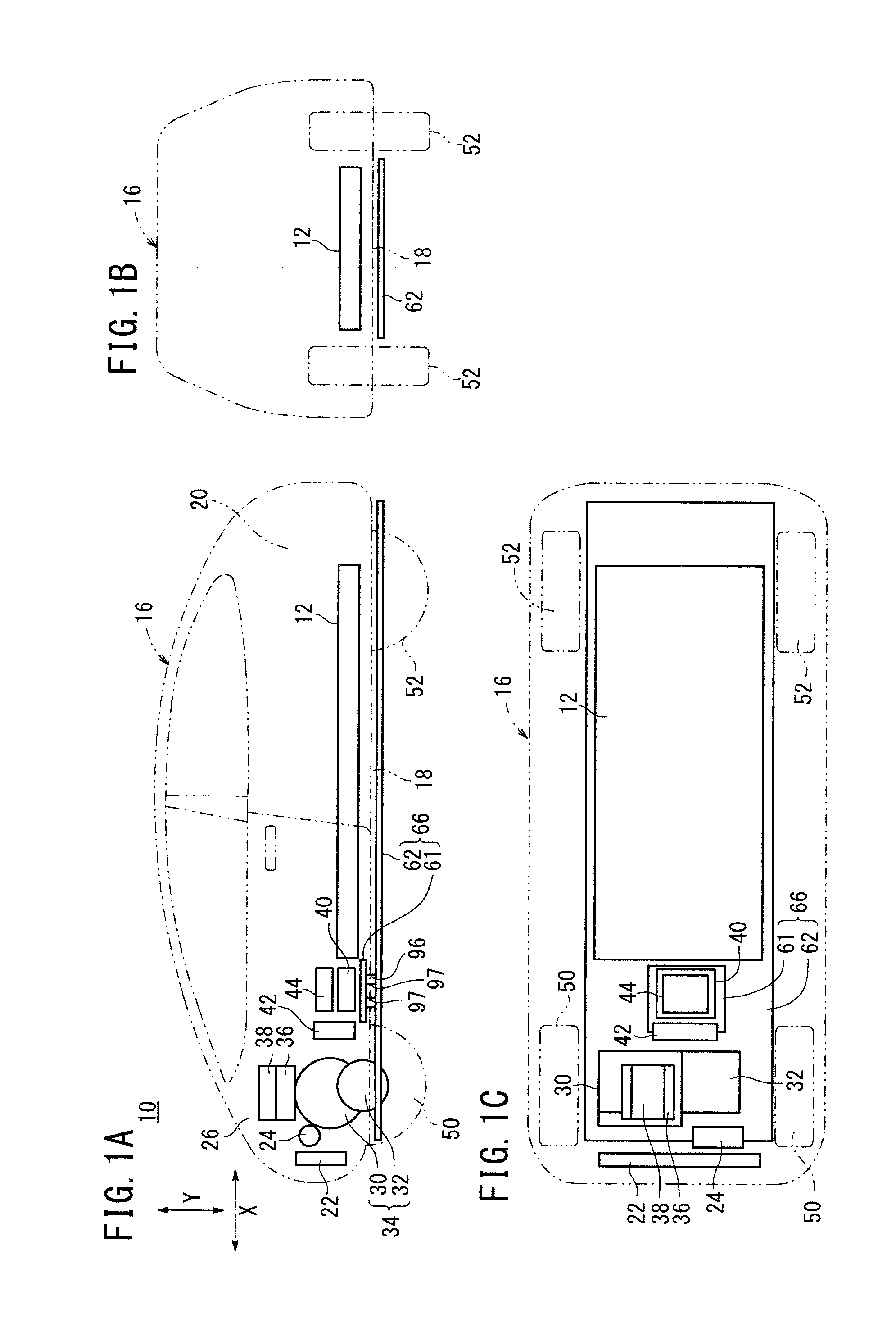
[0024]FIGS. 1A, 1B, and 1C are a side elevational view, a rear elevational view, and a plan view, respectively, showing transparently the layout of major vehicle-mounted components in an electric vehicle 10 according to an embodiment of the present invention.

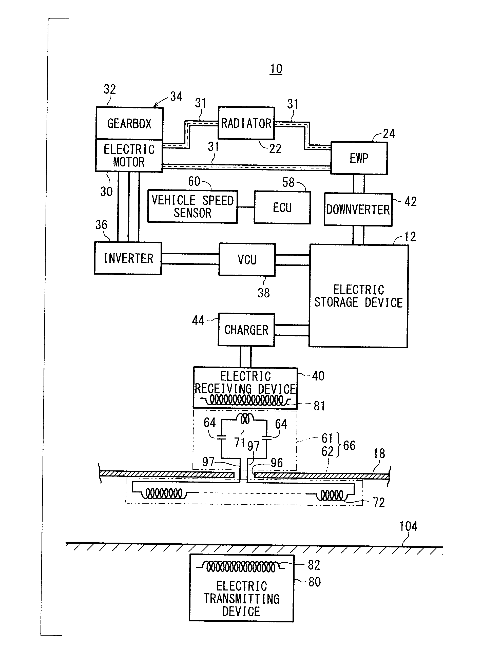
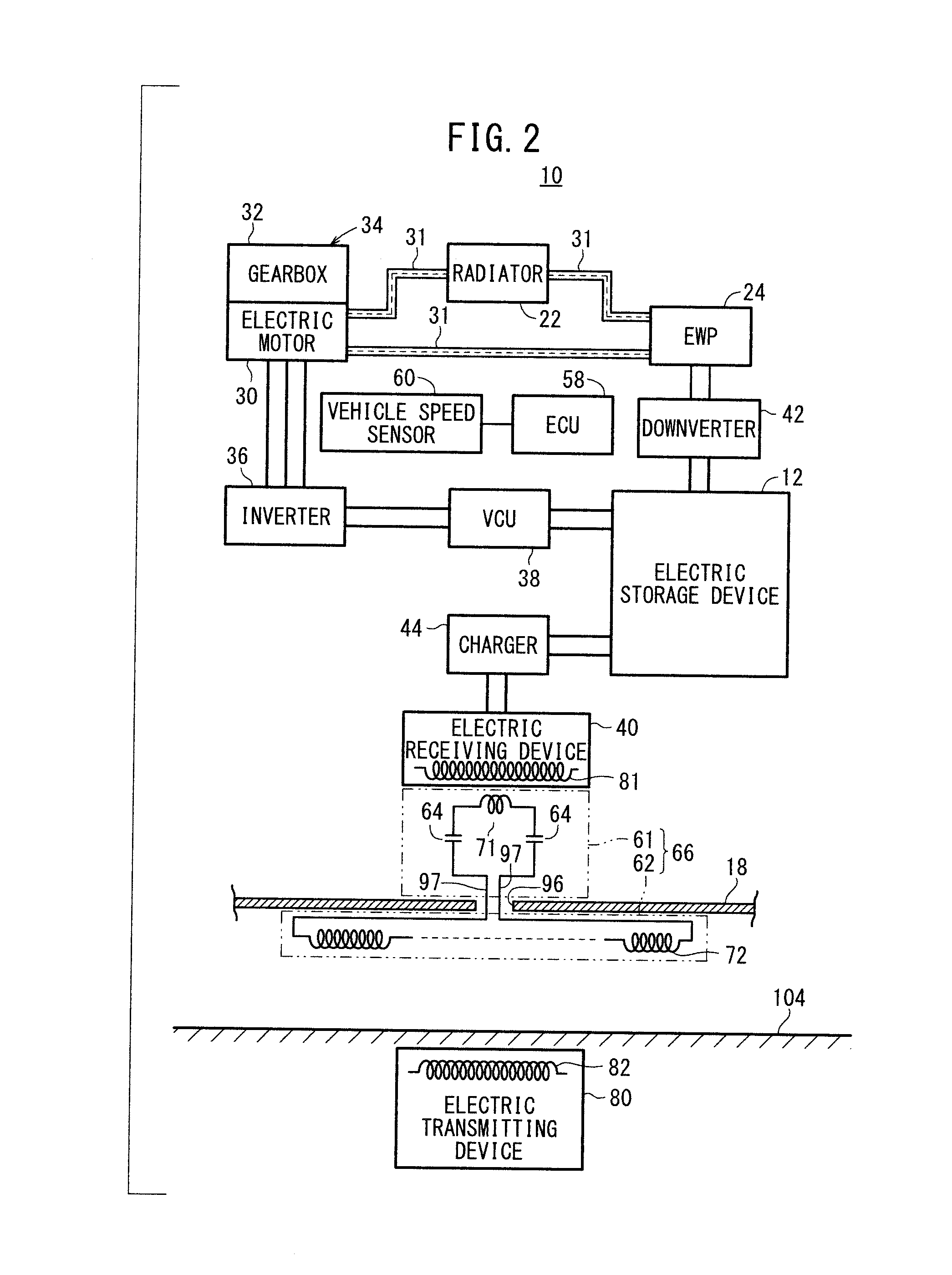
[0025]FIG. 2 is a schematic block diagram showing the vehicle-mounted major components, interconnections therebetween, and pipes in the electric vehicle 10 shown in FIGS. 1A, 1B, and 1C.

[0026]As shown in FIGS. 1A, 1B, and 1C, the electric vehicle 10 (vehicle) includes a high-voltage electric storage device 12 such as a lithium ion secondary battery, a capacitor, or the like. The electric storage device 12, which has a thin shape in the form of a rectangular parallelepiped, extends from a position beneath the front seats along an underfloor panel (vehicle underfloor panel) 18 of a vehicle body 16 to...


PUM


Abstract

Disclosed is an electric vehicle which receives power from a road surface by means of a wireless connection, in which an optimal configuration of a repeater (which is a resonator) and a receiving coil relative to the vehicle body is clarified. A first coil configuring the repeater forms a first wireless connection with a receiver coil, and a second coil forms a second wireless connection with a transmitting coil. The first coil is proximally arranged below the receiving coil and is aligned with the receiving coil, which is on the top side of a vehicle underbody panel; the second coil is arranged on the bottom side of the vehicle underbody panel. A performance indicator k*Q of the path from the transmitting coil below the road surface to the receiving coil of the electric vehicle is increased.

Description

TECHNICAL FIELD[0001]The present invention relates to an electric vehicle, which is propelled by drive power from an electric motor that is energized by electric power from an electric storage device, and more particularly, to an electric vehicle which is capable of being charged wirelessly (contactlessly charged).BACKGROUND ART[0002]Heretofore, electric vehicles have been known that travel based on a rotational torque transmitted to road wheels through a power transmitting mechanism from an electric motor that is energized by electric power from an electric storage device. Problems to be solved in order for such electric vehicles to find widespread use include the relatively small distance that such vehicles can travel with a single charging process performed on the electric storage device, lack of pervasive charging facilities, and long charging times, etc.[0003]Another concern in relation to electric vehicles is that, since electric accessories such as an air conditioner, etc., c...

Claims


Application Information

Patent Timeline
Patent Type & Authority Applications(United States)
IPC IPC(8): H02J7/00B60L11/18B60L9/00B60L5/00
CPCB60L5/005Y02T90/121B60L11/1803B60L11/182B60L11/1829B60L11/1831B60L2240/36B60M7/003H01M10/44H02J5/005Y02T10/7005Y02T10/7022Y02T90/12Y02T90/122Y02T90/125Y02T90/14B60K11/02B60K11/04B60L3/0061B60K2001/006B60K2001/0438B60L2210/12B60L2210/30B60L2240/12B60Y2400/61Y02T10/7241Y02T10/7233Y02T90/127B60L11/005Y02T10/7072B60L50/40B60L50/51B60L53/38B60L53/39B60L53/126Y02T10/70Y02T10/72Y02E60/10H02J50/90H02J50/502H02J50/12
Inventor ATARASHI, HIROFUMI
Owner HONDA MOTOR CO LTD
Why Eureka
Try Eureka