Vehicular lamp

a technology of vehicle lamps and lampshades, which is applied in the field of vehicle lamps, can solve the problems of increasing fabrication costs and achieve the effects of reducing fabrication costs, improving design performance, and simplifying the manufacturing steps

Inactive Publication Date: 2009-01-29
TOYODA GOSEI CO LTD
View PDF5 Cites 96 Cited by
  • Summary
  • Abstract
  • Description
  • Claims
  • Application Information

AI Technical Summary

Benefits of technology

[0015]According to the above-described constitution, the light of the first light source is reflected by the interface reflection of the reflecting portion of the lens rear face. On the other hand, the light of the second light source is reflected by the reflecting face, incident on a light guiding member from the transmitting portion of the lens rear face and is irradiated from the front light emitting face. The invention is constituted in this way, and therefore, the reflection treatment is not needed at the lens surface. Fabricating steps are simplified and fabrication cost is reduced. On the other hand, both of the light of the first light source and the light of the second light source are radiated from the front light emitting face of the lens. The light of the first light source and the light of the second light source are radiated from the same light emitting face in this way, and therefore, a unified feeling of a light emission mode is increased and a design performance is promoted.

Problems solved by technology

Therefore, fabricating steps increase, as a result, fabrication cost is increased.

Method used


Image

  • Vehicular lamp
  • Vehicular lamp
  • Vehicular lamp

Examples


example 1

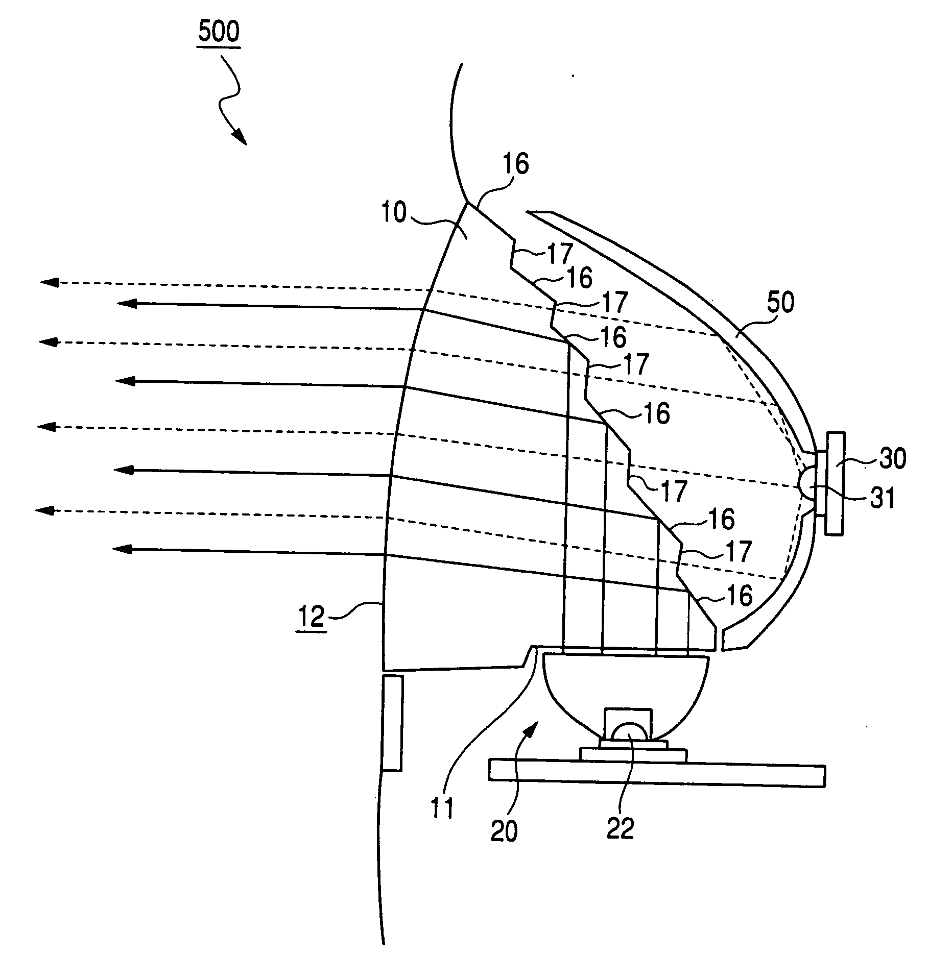
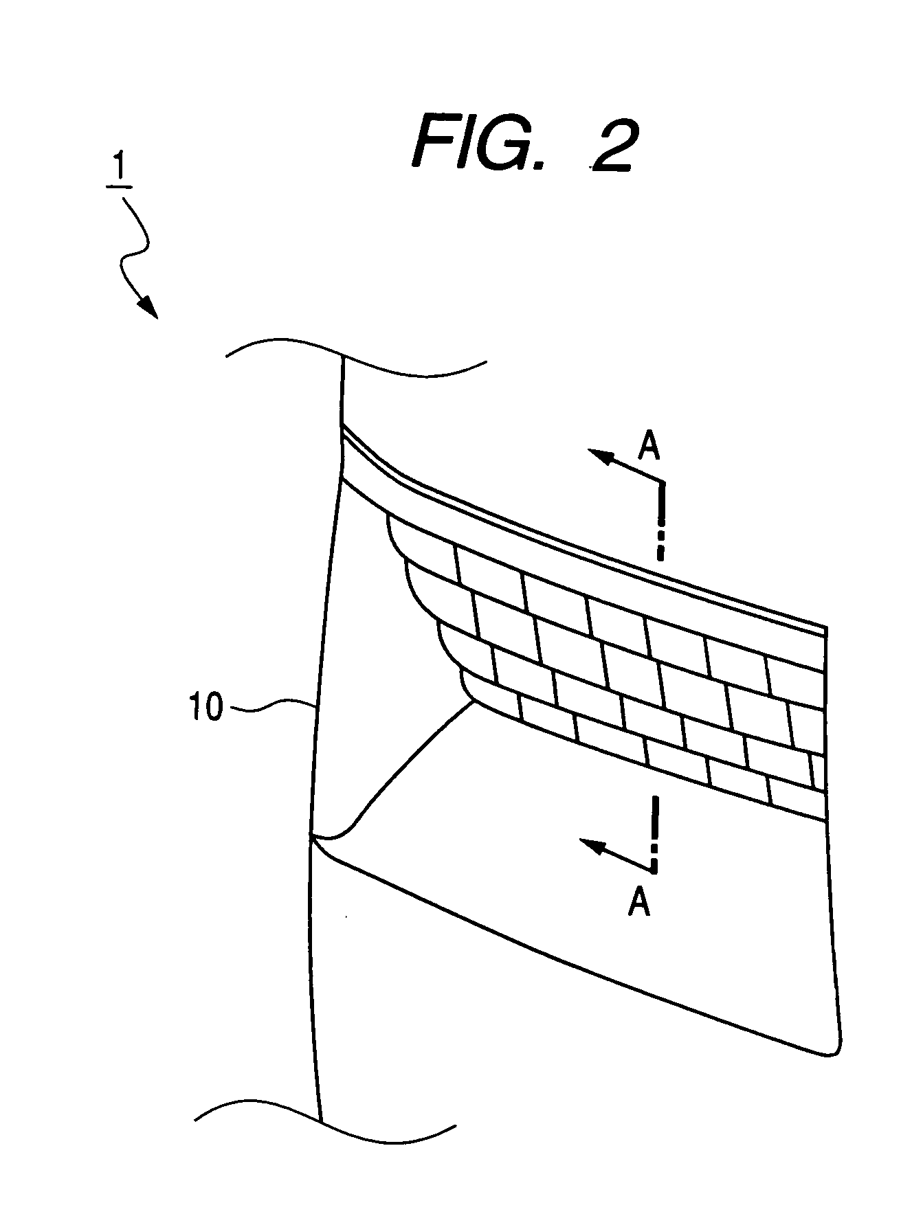
[0039]FIG. 2 is a perspective view showing a rear combination lamp 1 according to an example of the vehicular lamp of the invention. A sectional view of an A-A line position of FIG. 2 is shown in FIG. 3. As shown by FIG. 2, the rear combination lamp 1 includes a lens 10 made by acrylic resin having a refractive index of about 1.5, a first LED unit 20 opposed to a side end face 11, a second LED unit 30 arranged on a rear side of the first LED unit 20, and a housing 40. A front light emitting face 12 of the lens 10 is constituted by a gradually curved convex curved face. A radius of curvature of the curved face is 400 mm through 600 mm. The front light emitting face 12 satisfies the following equation when the refractive index of the lens 10 is designated by notation n, and an angle made by the front light emitting face 12 and the side end face 11 is designated by notation θ.

θ>2 sin−1(1 / n)  [Equation 4]

[0040]On the other hand, a thickness (distance between the front light emitting fac...


PUM


Abstract

The invention is constituted by a vehicular lamp characterized in a lens having a first light source, a second light source, a front light emitting face, a side end face to which the first light source is opposed, and a rear face, wherein the rear face includes a lens having pluralities of reflecting portions and transmitting portions consecutively aligned alternately in a direction of being remote from the side end face, and a reflecting face arranged on a rear side of the lens, light of the first light source is incident on the lens from the side end face of the lens, reflected by an interface of the reflecting portion, thereafter, radiated from the front light emitting face, and light of the second light source is reflected by the reflecting portion, thereafter, incident on the lens from the transmitting portion and radiated from the front light emitting face.

Description

BACKGROUND OF THE INVENTION[0001]1. Field of the Invention[0002]The present invention relates to a vehicular lamp. In details, the invention relates to an improvement in a vehicular lamp of a rear combination lamp or the like.[0003]2. Description of the Related Art[0004]According to a vehicular lamp of a rear combination lamp, a high mounted stop lamp or the like, generally, desired light emission is achieved by utilizing light of a plurality of kinds of light sources. For example, Patent Reference 1 discloses a rear combination lamp including two kinds of light sources (LED lamp for stop lamp and LED lamp for turn lamp) and a lens. According to the rear combination lamp, by subjecting a portion of a lens front face to metal vapor deposition, an outer reflecting portion is formed. On the other hand, a portion of a lens rear face is inclined and an inner reflecting portion is formed by an interface thereof. Further, a stop lamp is lighted by reflecting light of an LED lamp for a stop...

Claims


Application Information

Patent Timeline
Patent Type & Authority Applications(United States)
IPC IPC(8): F21S8/10F21V7/00
CPCB60Q1/0058B60Q1/2607F21S48/215F21S48/225F21S48/2262F21Y2101/02F21S48/236F21S48/24F21V7/0008F21V7/0091F21S48/2281F21Y2115/10F21S43/14F21S43/249F21S43/315F21S43/40F21S43/245F21S43/239F21S43/26
Inventor MISAWA, AKIHIROOBA, TATSUYAARAKAWA, TETSUYAISHIKAWA, AKIHIKO
Owner TOYODA GOSEI CO LTD
Why Eureka
Try Eureka