Method of manufacturing liquid discharge head

a technology of liquid discharge head and manufacturing method, which is applied in the direction of recording equipment, instruments, and recording information storage, can solve the problems of reducing steps, and achieve the effects of simplifying steps, low cost, and simplifying manufacturing steps

Inactive Publication Date: 2007-11-27
CANON KK
View PDF12 Cites 38 Cited by
  • Summary
  • Abstract
  • Description
  • Claims
  • Application Information

AI Technical Summary

Benefits of technology

[0009]The present invention has been developed in view of the above-described problem, and an object thereof is to provide a method of manufacturing a liquid discharge head, in which it is possible to easily manufacture the liquid discharge head capable of bearing use over a long period and having an excellent reliability.
[0010]In addition to the above-described object or separately from the object, another object of the present invention is to provide a manufacturing method in which manufacturing steps can be simplified to thereby manufacture an excellent liquid discharge head at low cost.
[0012]According to the method of manufacturing the liquid discharge head in the present invention, since there is disposed, between the substrate and the flow path wall, the adhesive layer made of the polyether amide resin for improving a close contact property between the substrate and the flow path wall, there is not a problem that the flow path forming member does not peel from the substrate during the use over a long period. Furthermore, as the flow path wall, resist for patterning the polyether amide resin is utilized as such, and this can reduce the steps. In consequence, it is possible to provide the method of manufacturing the liquid discharge head, in which it is possible to easily manufacture the liquid discharge head capable of bearing the use over the long period and having an excellent reliability.
[0014]According to the method of manufacturing the liquid discharge head in the other aspect of the present invention, a member which protects the surface of the substrate does not have to be disposed separately, when the mask for forming the ink supply port is formed on the back of the substrate. This can simplify the steps. In consequence, it is possible to provide the manufacturing method in which the manufacturing steps can be simplified to thereby manufacture the excellent liquid discharge head at low cost.

Problems solved by technology

Furthermore, as the flow path wall, resist for patterning the polyether amide resin is utilized as such, and this can reduce the steps.

Method used


Image

  • Method of manufacturing liquid discharge head
  • Method of manufacturing liquid discharge head
  • Method of manufacturing liquid discharge head

Examples


first embodiment

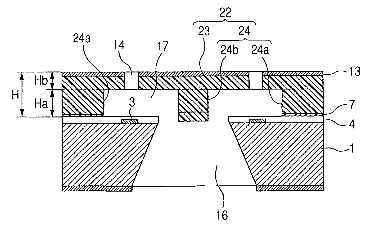
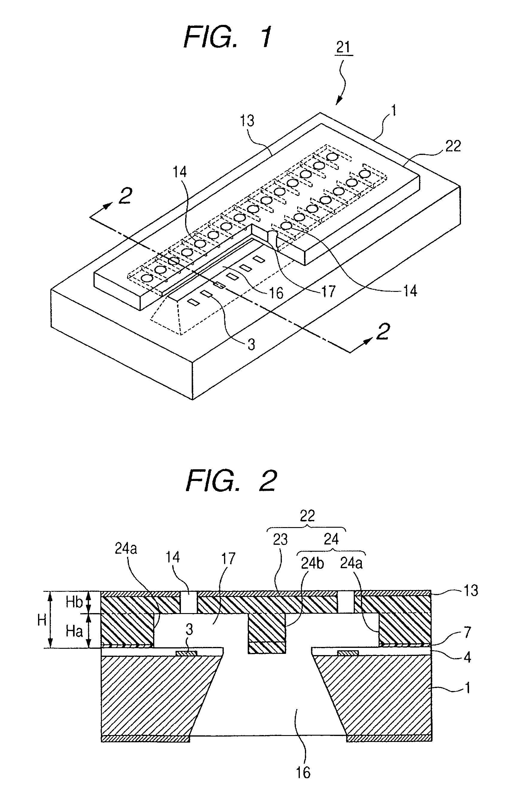
[0023]A first embodiment of the present invention will be described with reference to the drawings. First, there will be described a schematic constitution of an ink jet recording head (liquid discharge head) to which the present invention is applied. FIG. 1 is a partially broken perspective view showing a part of the ink jet recording head to which the present invention is applied. FIG. 2 is a schematic sectional view of the ink jet recording head cut along the 2-2 line of FIG. 1.

[0024]The present ink jet recording head is mountable on a device such as a printer, a photocopier, a facsimile machine having a communication system or a word processor having a printer unit, or an industrial recording device combined with various types of processing devices in a composite manner. The present ink jet recording head can perform recording on various recording mediums made of paper, thread, fiber, leather, metal, plastic, glass, wood, ceramic and the like. It is to be noted that in the prese...

second embodiment

[0041]Next, a second embodiment of the present invention will be described with reference to FIGS. 4A to 4E. The present embodiment is different from the first embodiment in a pattern shape of a adhesive layer. FIGS. 4A to 4E are schematic sectional views showing a main part of a process of manufacturing a recording head in the second embodiment of the present invention. Each drawing of FIGS. 4A to 4E are sectional views cut along the 2-2 line of FIG. 1, and is shown from the same direction as that of FIG. 2 or FIGS. 3A to 3H.

[0042]There will be described hereinafter a different respect of the present embodiment from the above first embodiment.

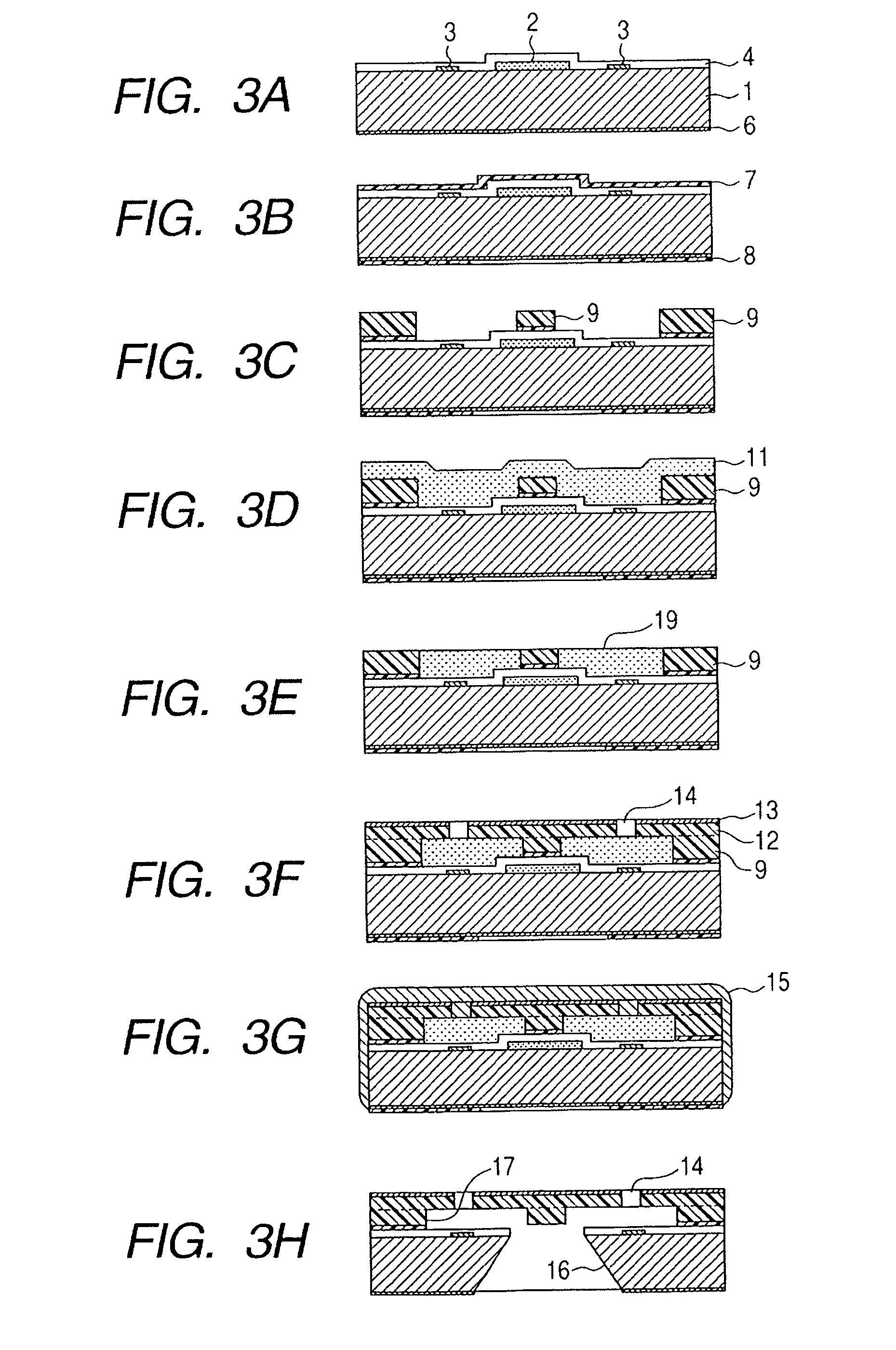
[0043]First, as shown in FIG. 4A, there is prepared a substrate 1 including ink discharge energy generating elements 3, a sacrifice layer 2, a protective film 4 and an SiO2 film 6. Next, as shown in FIG. 4B, a polyether amide resin layer 7 is applied to the surface of the substrate 1, and a polyether amide resin layer 8 is applied to the back ...

third embodiment

[0047]Next, a third embodiment of the present invention will be described with reference to FIGS. 6A to 6I. The present embodiment is different from the first embodiment in a step of forming a mask of an ink supply port. FIGS. 6A to 6I are schematic sectional views showing a main part of a process of manufacturing a recording head in the third embodiment of the present invention. Each drawing of FIGS. 6A to 6I are sectional views cut along the 2-2 line of FIG. 1, and is shown from the same direction as that of FIG. 2 or FIGS. 3A to 3H.

[0048]There will be described hereinafter a different respect of the present embodiment from the above first embodiment.

[0049]First, as shown in FIG. 6A, there is prepared a substrate 1 including ink discharge energy generating elements 3, a sacrifice layer 2, a protective film 4 and an SiO2 film 6. Next, as shown in FIG. 6B, a polyether amide resin layer 7 is applied to the surface of the substrate 1 by spin coating or the like, and the substrate is b...


PUM

PropertyMeasurementUnit
energyaaaaaaaaaa
photosensitiveaaaaaaaaaa
discharge energyaaaaaaaaaa

Abstract

The method of manufacturing a recording head has a flow path wall forming step of forming flow path walls on a substrate having energy generating elements formed thereon, an imbedded material depositing step of depositing an imbedded material between the flow path walls and on a top of each flow path wall, a flattening step of polishing a top of the deposited imbedded material, until the top of the flow path wall is exposed, and a step of forming an orifice plate on the tops of the polished imbedded material and the exposed flow path wall. In the step of forming the flow path walls, patterning of a close contact property improvement layer is simultaneously performed to improve a close contact property between the flow path wall and the substrate.

Description

BACKGROUND OF THE INVENTION[0001]1. Field of the Invention[0002]The present invention relates to a method of manufacturing a liquid discharge head, more particularly to a method of manufacturing a liquid path forming member of a liquid discharge head.[0003]2. Related Background Art[0004]In recent years, there have increasingly progressed miniaturization and densification of a liquid discharge head represented by an ink jet recording head. In the ink jet recording head in which an ink discharge port is disposed so as to face an energy generating element to generate energy for discharging ink, the energy generating element, an electric control circuit which drives this element and the like are formed on a substrate by use of a semiconductor manufacturing technology.[0005]In a highly functional ink jet recording head, as a method of supplying the ink to a plurality of ink discharge ports (nozzles), there is adopted a structure in which an ink supply port is formed so as to extend throu...

Claims


Application Information

Patent Timeline
Patent Type & Authority Patents(United States)
IPC IPC(8): B41J2/05H01L21/00
CPCB41J2/1603B41J2/1628B41J2/1629B41J2/1631B41J2/1645B41J2/1635B41J2/1639B41J2/164B41J2/1632
Inventor MURAYAMA, HIROYUKIKOYAMA, SHUJITAGAWA, YOSHINORIFUJII, KENJIOHSUMI, MASAKIURAYAMA, YOSHINOBUYAMAMURO, JUNTAKAHASHI, TSUYOSHIWATANABE, MASAHISA
Owner CANON KK
Why Eureka
Try Eureka