Radiofrequency perforation apparatus

a radiofrequency perforation and apparatus technology, applied in the field of radiofrequency perforation apparatus, can solve the problems of increasing the risk of causing damage to non-target areas in the heart, difficult to create perforations therein, and accidental puncture or piercing of heart areas other than the target tissue, so as to improve the rapidity and precision of radiofrequency perforation, improve patient comfort, and contribute to the effect of torquability and pushability

Active Publication Date: 2012-06-05
BOSTON SCI MEDICAL DEVICE LTD
View PDF8 Cites 60 Cited by
  • Summary
  • Abstract
  • Description
  • Claims
  • Application Information

AI Technical Summary

Benefits of technology

[0007]Advantageously, the proposed radiofrequency perforation apparatus provides useful tactile feedback to the intended user, as well as contributing to the torquability and pushability of the proposed radiofrequency perforation apparatus, which improves the rapidity and precision of the radiofrequency perforation performed with the proposed radiofrequency perforation apparatus. In turn, this increases patient comfort and reduces risks of injuring the patient. Also, in some embodiments of the invention, the proposed radiofrequency perforation apparatus nevertheless remains flexible enough that it can be inserted percutaneously.

Problems solved by technology

Due to the mechanical force required to use this device, as well as the sharp tip of this device, it is not uncommon for users to accidentally puncture or pierce areas of the heart other than the target tissue.
Furthermore, in certain cases, the septum may be thickened or tough, such that it may be difficult to create a perforation therein.
In these instances, extra mechanical force may be required to perforate the septum, thereby increasing the risk of causing damage to non-target areas in the heart.
However, these apparatuses are typically relatively flexible, and therefore deprive their intended users of important tactile feedback that they are used to have with needles.

Method used


Image

  • Radiofrequency perforation apparatus
  • Radiofrequency perforation apparatus
  • Radiofrequency perforation apparatus

Examples


Embodiment Construction

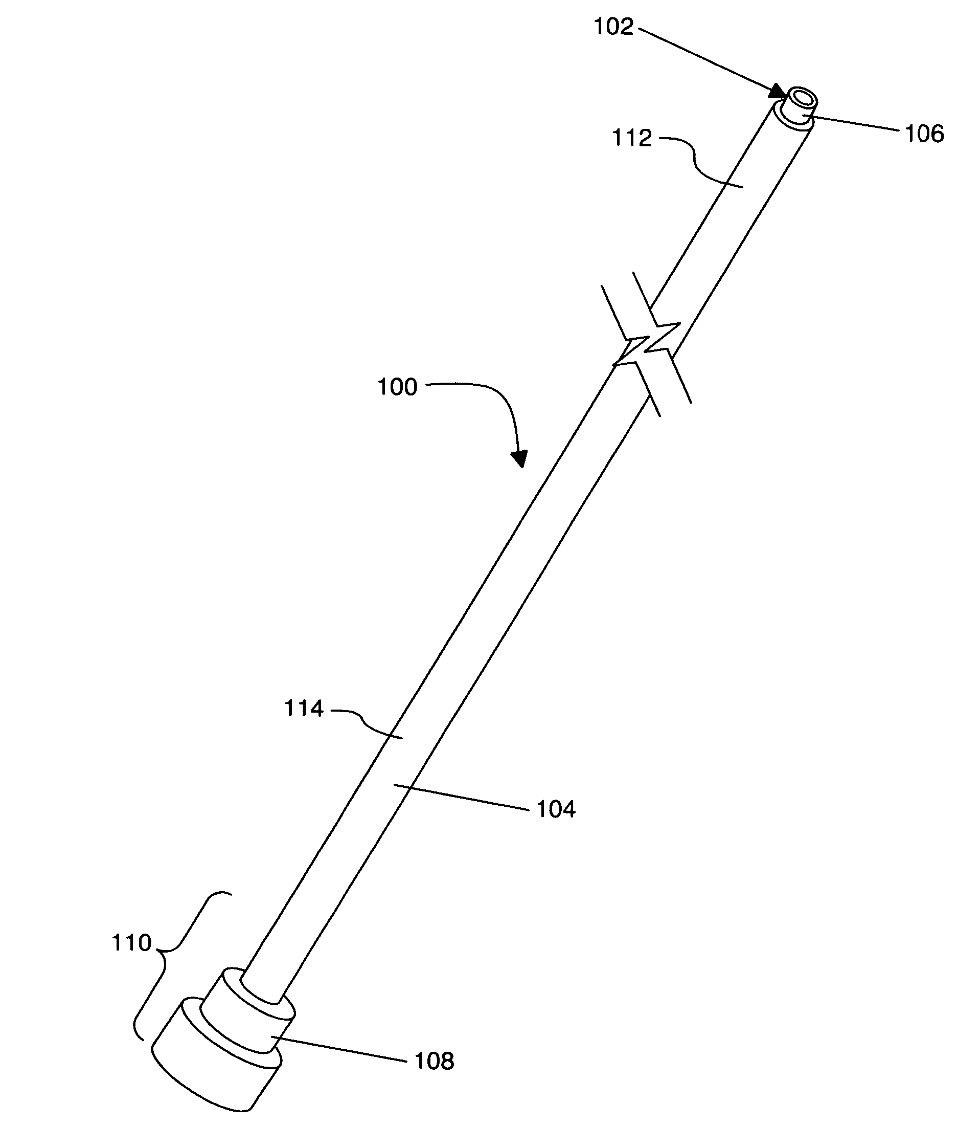
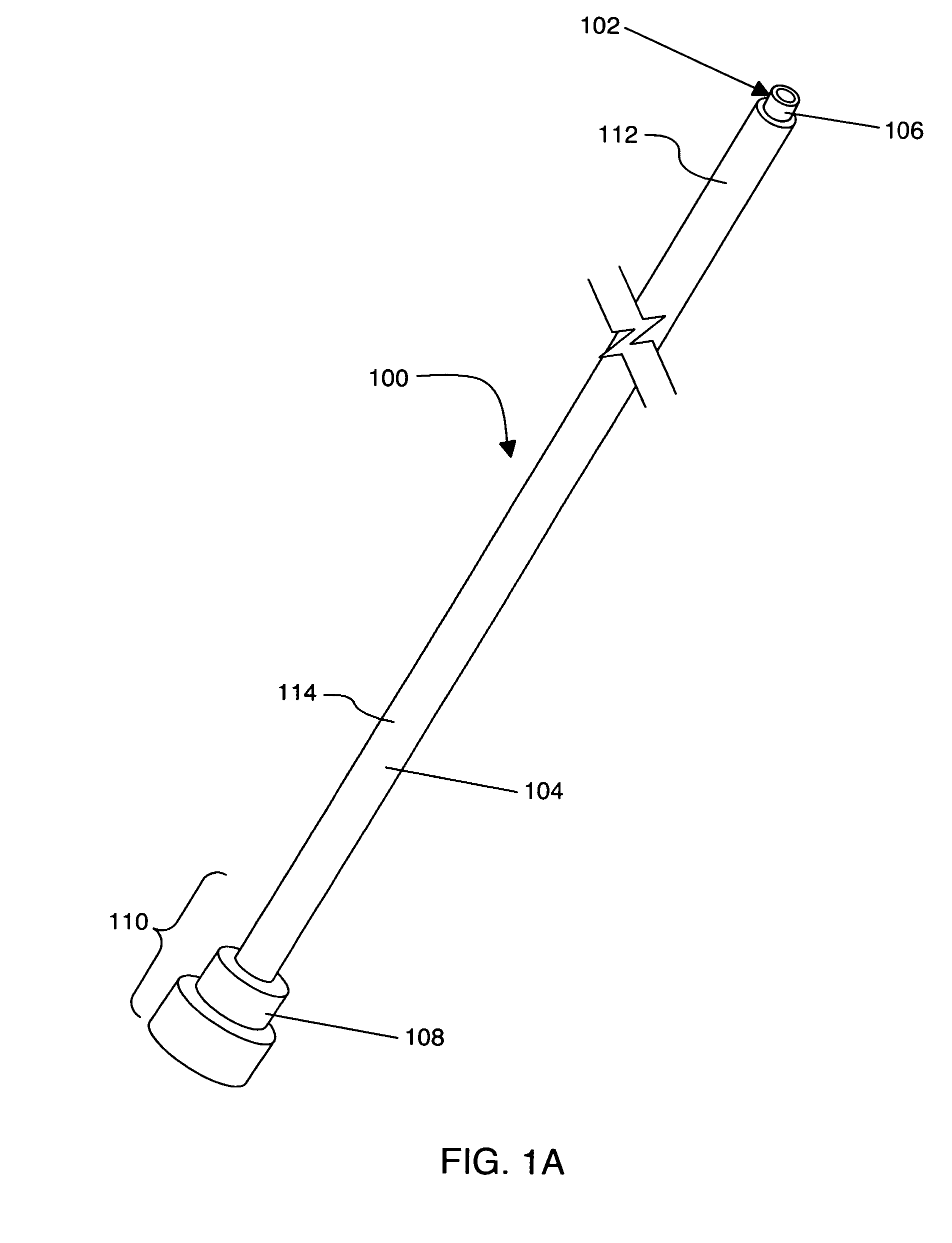
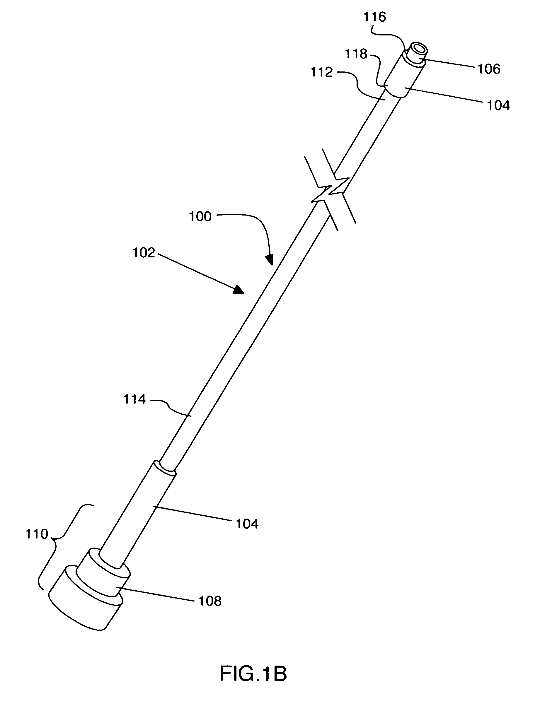
[0027]With specific reference now to the drawings in detail, it is stressed that the particulars shown are by way of example and for purposes of illustrative discussion of embodiments of the present invention only. In this regard, no attempt is made to show structural details of the invention in more detail than is necessary for a fundamental understanding of the invention, the description taken with the drawings making apparent to those skilled in the art how the several forms of the invention may be embodied in practice.

[0028]Before explaining at least one embodiment of the invention in detail, it is to be understood that the invention is not limited in its application to the details of construction and the arrangement of the components set forth in the following description or illustrated in the drawings. The invention is capable of other embodiments or of being practiced or carried out in various ways. Also, it is to be understood that the phraseology and terminology employed he...


PUM


Abstract

A radiofrequency perforation apparatus for creating a channel at a target location in a body of a patient, the radiofrequency perforation apparatus being usable by an intended user having a hand, the radiofrequency perforation apparatus comprising: a handle graspable by the hand; a distal portion, the distal portion defining a distal portion length, the distal portion including an electrode and an electrical insulator extending from the electrode; and a force transmitting portion extending between the distal portion and the handle, the force transmitting portion defining a force transmitting portion length, the force transmitting portion length being larger than the distal portion length, the force transmitting portion having a force transmitting portion flexural rigidity of at least about 0.016 Nm2; whereby the force transmitting portion has a force transmitting portion flexural rigidity allowing the transmission to the handle of contact forces exerted on the distal portion when the distal portion contacts the target location to provide tactile feedback to the intended user.

Description

CROSS-REFERENCES TO RELATED APPLICATIONS[0001]This application claims the benefit of: U.S. provisional application No. 60 / 827,452, filed on Sep. 29, 2006, and U.S. provisional application No. 60 / 884,285, filed on Jan. 10, 2007, both of which are incorporated by reference herein in their entirety.FIELD OF THE INVENTION[0002]The present invention relates generally to methods and devices usable to deliver energy within the body of a patient. More specifically, the present invention is concerned with a radiofrequency perforation apparatus.BACKGROUND OF THE INVENTION[0003]Devices currently exist for creating a puncture, channel, or perforation within a tissue located in a body of a patient. One such device is the Brockenbroughâ„¢ Needle of Medtronic Inc., which is commonly used to puncture the septum of the heart. This device is a stiff elongate needle, which is structured such that it may be introduced into a body of the patient via the femoral vein, and directed towards the heart. Due to...

Claims


Application Information

Patent Timeline
Patent Type & Authority Patents(United States)
IPC IPC(8): A61B18/18
CPCA61B18/1482A61B18/1492A61B2018/00011A61B2018/00083A61B2018/00351A61B2018/00839A61B2019/464A61B2218/002A61B2090/064
Inventor MIRZA, MAHMOODDAVIES, GARETH
Owner BOSTON SCI MEDICAL DEVICE LTD
Why Eureka
Try Eureka