System and method for locating fluid leaks at a drape using sensing techniques

a technology of sensing and fluid leakage, applied in the field of tissue growth promotion system and method, can solve the problems of reducing the performance of the reduced pressure delivery system, unable to realize full treatment potential, and difficulty in identifying the precise location of fluid leakage, and achieve optimal therapeutic effects

Active Publication Date: 2011-10-06
3M INNOVATIVE PROPERTIES CO
View PDF7 Cites 89 Cited by
  • Summary
  • Abstract
  • Description
  • Claims
  • Application Information

AI Technical Summary

Benefits of technology

[0008]To overcome the problem of locating fluid leaks of a drape being used on a tissue site of a patient, the principles of the present invention provide for detecting location of and correcting fluid leaks at the drape of reduced pressure delivery systems. More specifically, the principles of the present invention provide for using one or more image sensing techniques (e.g., IR sensing, UV sensing, and temperature sensing) for locating fluid leak locations of the drape. By being able to locate fluid leaks at the drape (e.g., at an interface between the drape and tissue of the patient), optimum therapeutic results may be produced.
[0009]One embodiment of a process for determining location of a fluid leak at a drape of a reduced pressure delivery system being used on a tissue site of a patient may include applying a reduced pressure to the tissue site of the patient. The drape may be imaged to generate image data, and a determination of a location of a fluid leak of the drape may be made from the image data. As a result of the determination of the location of the fluid leak, the drape may be corrected. The imaging may be made in a non-visible spectrum. The non-visible spectrum may be in an IR spectrum or UV spectrum. In one embodiment, a fluid, such as compressed air, may be applied to the dressing via the interface between the drape and tissue of the patient to improve imaging in the non-visible spectrum.

Problems solved by technology

In the event that a fluid leak results during installation of the drape or during treatment, clinicians often find it difficult to isolate the precise location of the fluid leak.
If the fluid leak is not corrected, then the performance of the reduced pressure delivery system is reduced and full treatment potential is not realized.

Method used


Image

  • System and method for locating fluid leaks at a drape using sensing techniques
  • System and method for locating fluid leaks at a drape using sensing techniques
  • System and method for locating fluid leaks at a drape using sensing techniques

Examples


Embodiment Construction

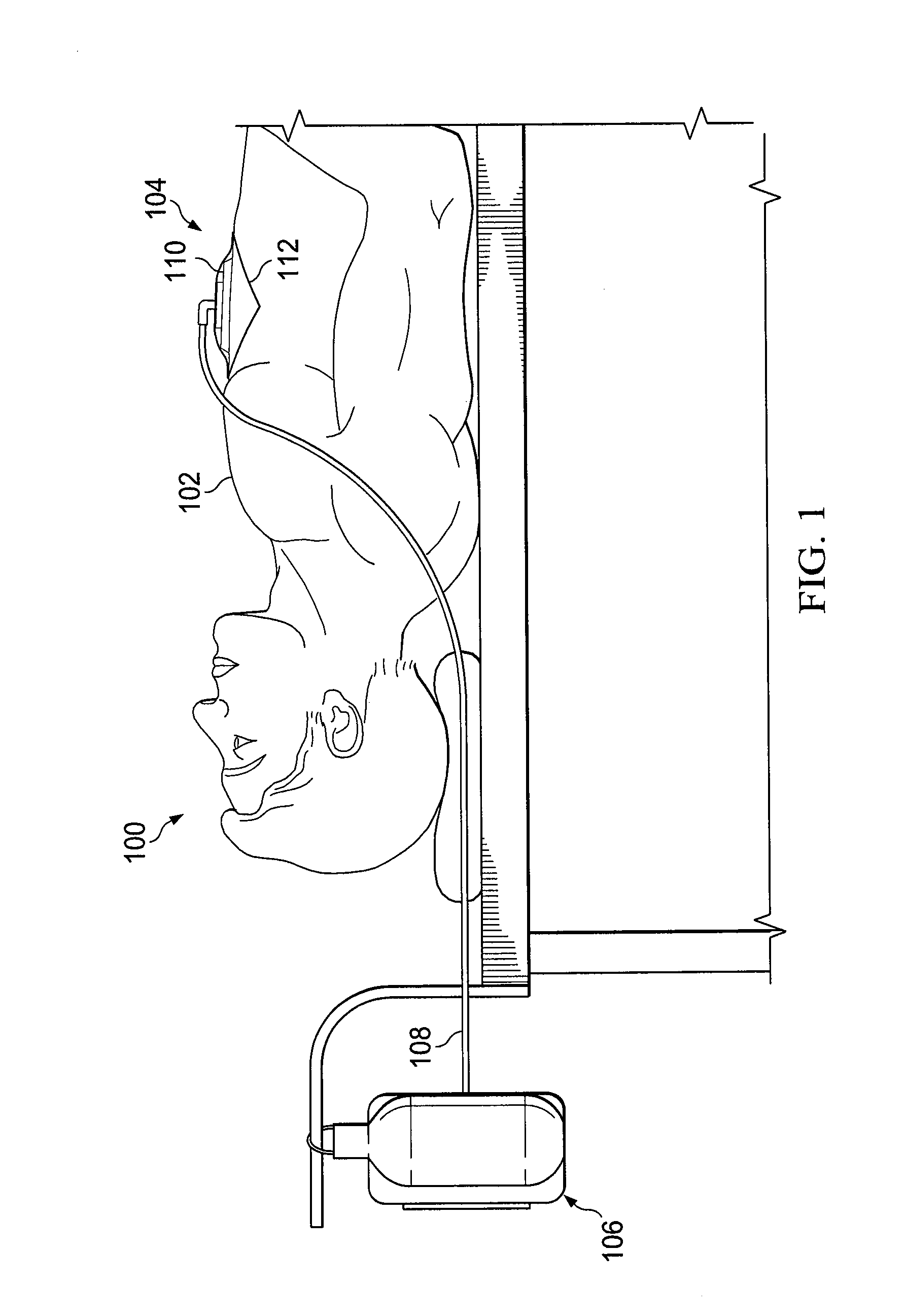
[0023]With regard to FIG. 1, a setup 100 for treating a patient 102 is shown. The patient is receiving reduced pressure treatment at a tissue site 104 by a reduced pressure delivery system 106. The reduced pressure delivery system 106 includes a reduced pressure conduit 108 that extends from the reduced pressure delivery system 106 to the tissue site 104. At the tissue site 104, a reduced pressure dressing or distribution manifold 110 may be fluidly connected to the reduced pressure conduit 108. In addition, a drape 112 may be placed over the tissue site 104 and distribution manifold 110. The drape 112 may be a flexible material that is impermeable to gases to prevent air or other fluids from entering or exiting the tissue site 104 during reduced pressure treatment. In one embodiment, the drape is a transparent film having an adhesive around the perimeter, as understood in the art. Alternative embodiments of the drape may be utilized in accordance with the principles of the present ...


PUM


Abstract

A system and method for determining location of a fluid leak at a drape of a reduced pressure delivery system being used on a tissue site of a patient may include applying a reduced pressure to the tissue site of the patient. The drape may be imaged to generate image data, and a determination of a location of a fluid leak of the drape may be made from the image data. As a result of the determination of the location of the fluid leak, the drape may be corrected. The imaging may be made in a non-visible spectrum. The non-visible spectrum may be in an IR spectrum or UV spectrum. In one embodiment, a fluid, such as compressed air, may be applied to the dressing via the interface between the drape and tissue of the patient to improve imaging in the non-visible spectrum.

Description

CROSS-REFERENCE TO RELATED APPLICATIONS[0001]This application claims the benefit of U.S. Provisional Application No. 61 / 319,344, filed Mar. 31, 2010, which is incorporated herein by reference in its entirety.BACKGROUND OF THE INVENTION[0002]1. Field of the Invention[0003]This invention relates generally to a system and method of promoting tissue growth, and more specifically, a method for detecting and correcting fluid leaks at a drape positioned at a tissue site being treated by a reduced pressure delivery system.[0004]2. Description of Related Art[0005]Tissue growth and wound healing of patients has been shown to be accelerated through the use of applying reduced pressure to a tissue site. Reduced pressure delivery systems operate to form such a reduced pressure at a tissue site of a patient. This form of wound healing can be readily integrated into a clinician's wound healing procedures. Reduced pressure tissue therapy optimizes patient care and decreases costs associated with tr...

Claims


Application Information

Patent Timeline
Patent Type & Authority Applications(United States)
IPC IPC(8): A61B6/00
CPCA61M1/0088A61M2205/15A61M1/0025G01M3/20G01M3/002A61M1/73A61M1/96A61B34/10A61B1/041A61B1/05A61B5/0059H04N7/18A61M2205/3313A61M2205/3337A61M2205/3344A61M2205/3368A61M2205/3584A61M2205/44A61M2205/50A61M2205/502A61M2205/505A61M2205/584A61M2205/75
Inventor ROBINSON, TIMOTHY MARKLOCKE, CHRISTOPHER BRIAN
Owner 3M INNOVATIVE PROPERTIES CO
Why Eureka
Try Eureka