CMC Component Cooling Cavities

a technology of components and cooling cavities, which is applied in the direction of blade accessories, machines/engines, climate sustainability, etc., can solve the problems of increasing the likelihood of material failure, and increasing the negative impact of increased combustion gas temperatures, so as to reduce the amount of

Active Publication Date: 2020-03-12
GENERAL ELECTRIC CO
View PDF9 Cites 3 Cited by
  • Summary
  • Abstract
  • Description
  • Claims
  • Application Information

AI Technical Summary

Benefits of technology

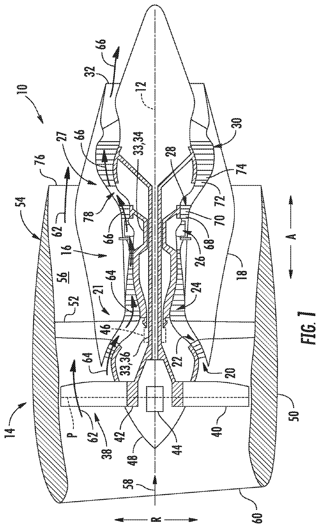
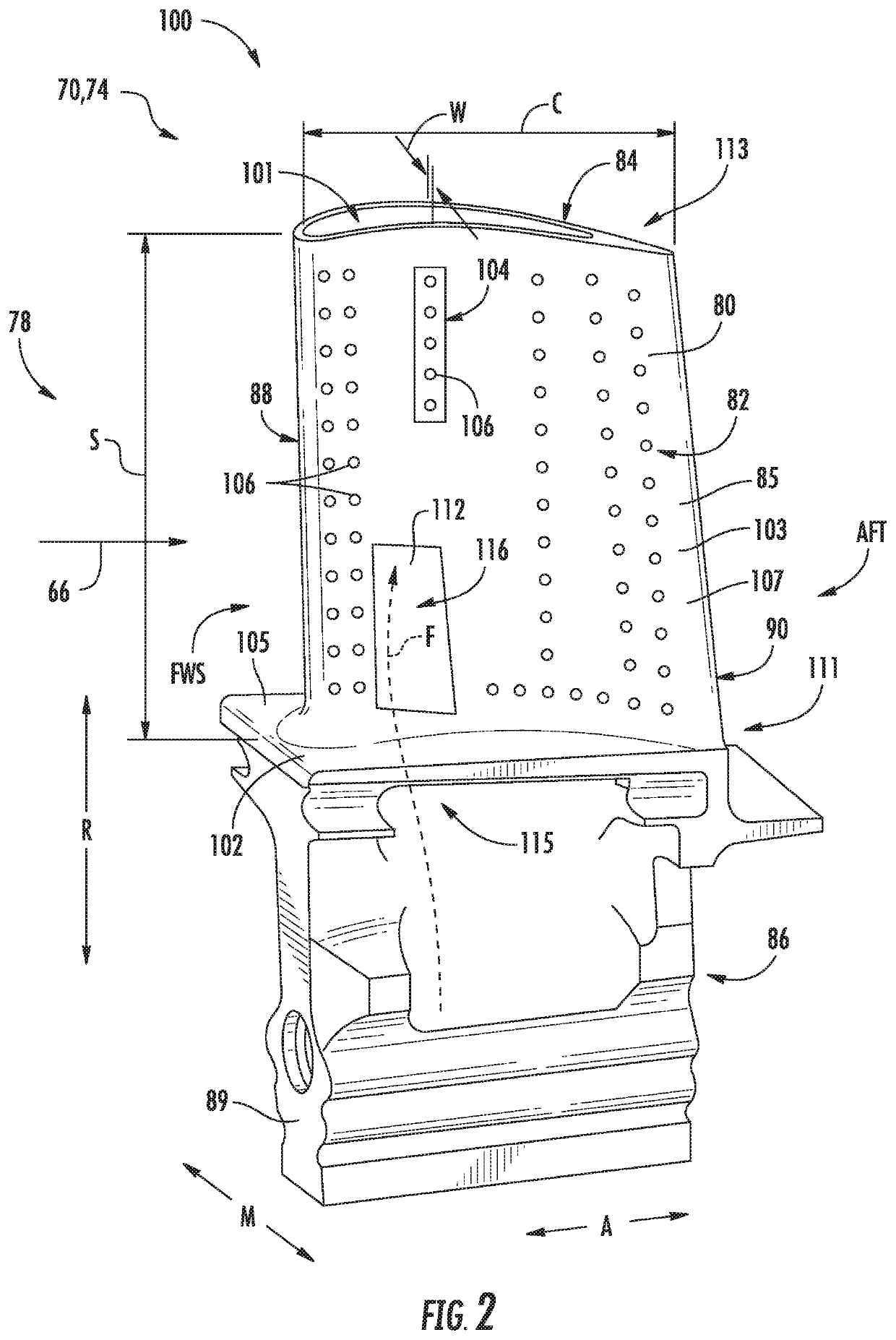
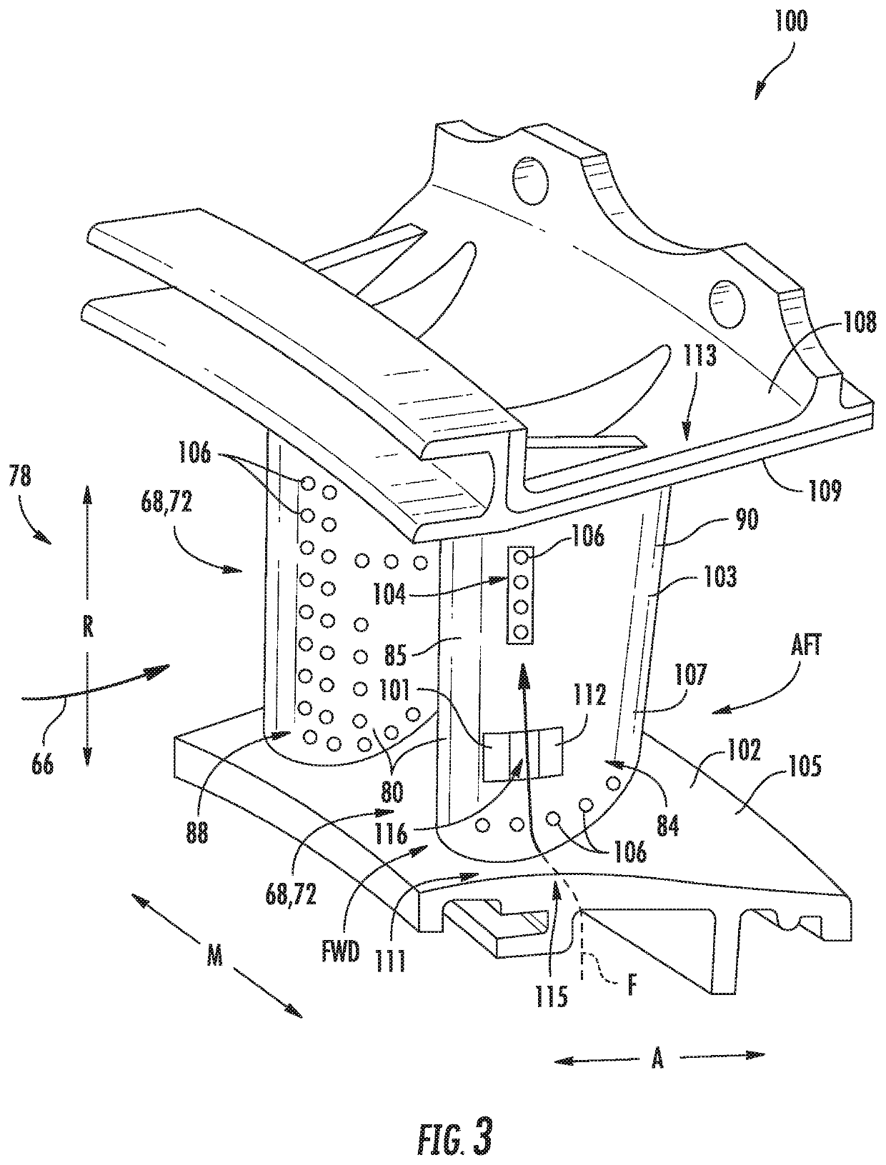
[0012]It should be recognized that the component may at least partially define and / or abut a flowpath for hot combustion gas through the gas turbine engine. As such, the compressed, cool air may cool the component and / or provide a protective film of compressed, cool air to reduce the temperature of the component. It should also be recognized that the compressed, cool air may cool the component via bore cooling. For instance, the flow of the compressed, cool air through the cooling cavity and / or film holes may cool the component.
[0014]In another embodiment, the component may be a turbine stator vane. In such embodiments, the outer enclosure may define an airfoil extending from the first end. The turbine stator vane may further include an inner band positioned at the first end of the turbine stator vane. Further, the turbine stator vane may include an outer band positioned at the second end of the turbine stator vane. As such, the airfoil may extend between the inner band and the outer band. It should be recognized that the inner band and outer band may at least partially define the flowpath for the hot combustion gasses from the combustion section of the gas turbine engine. Further, the stator vane may direct the hot combustion gas and / or increase the speed of the hot combustion gas, thereby increasing a dynamic pressure of the hot combustion gasses while reducing a static pressure of the hot combustion gas.
[0019]In a still further embodiment, at least one of the core or the outer enclosure may be formed from a ceramic matrix composite material. For instance, both the core and the outer enclosure may be formed from a ceramic matrix composite material. In embodiments where the core is formed from a ceramic matrix composite, the cooling cavity may be green machined on the core while the core is in a green state. For example, the core in the green state may be only partially cured. It should be recognized that the core in the green state may be more pliable, less brittle, and less rigid than a fully cured ceramic matrix composite core. As such, a core in the green state may be more easily machined allowing more complex cooling cavities to be formed on the exterior surface of the core. It should be further understood that the component may further include any of the additional features as described herein.
[0021]The partially formed component also includes an outer enclosure including an outer surface. The outer enclosure is positioned outside the core and extends from the first end of the core along at least a portion of the length of the core. Additionally, the outer enclosure at least partially defines the cooling cavity and abuts the filler material such that the outer enclosure secures the filler material within the cooling cavity. As such, the filler material prevents the cooling cavity from collapsing during a process to finish forming the partially formed component. The filler material at least partially dissipates during the process to finish forming the partially formed component.
[0024]In a still further embodiment, the filler material may include at least one of a polymer matrix, a x-linked polyvinyl butyral, a poly paraphenylene terephthalamide (e.g., Kevlar® from E. I. du Pont de Nemours and Company), or a low melting temperature alloy (e.g., a bismuth-tin alloy). Such filler material(s) may dissolve and / or dissipate when exposed to high temperatures, such those used during the process to finish forming the partially formed component. It should be recognized that, in other embodiments, the filler material may include any material that dissolves and / or dissipates during the process to finish forming the partially formed component. In another embodiment, the filler material may further include boron nitride. For instance, a boron nitride doped outer layer may at least partially envelop the filler material. The boron nitride may reduce the amount of or prevent certain materials, such as silicon, from filling the cooling cavity during the process to finish forming the partially formed component. It should be further understood that the partially formed component may further include any of the additional features as described herein.

Problems solved by technology

However, increased combustion temperatures can negatively impact the gas turbine engine components, for example, by increasing the likelihood of material failures.
However, even though CMC components may withstand more extreme temperatures than typical components, CMC components still may require cooling features or reduced exposure to the combustion gases to decrease a likelihood of negative impacts of increased combustion gas temperatures, e.g., material failures or the like.
Though many benefits may be realized by utilizing CMC components, CMC materials may have drawbacks.
In addition, cooling features, cavities, and / or conduits with complex, intricate geometry may be particularly difficult to form in CMC components.

Method used


Image

  • CMC Component Cooling Cavities
  • CMC Component Cooling Cavities
  • CMC Component Cooling Cavities

Examples


Embodiment Construction

[0036]Reference now will be made in detail to embodiments of the invention, one or more examples of which are illustrated in the drawings. Each example is provided by way of explanation of the invention, not limitation of the invention. In fact, it will be apparent to those skilled in the art that various modifications and variations can be made in the present invention without departing from the scope or spirit of the invention. For instance, features illustrated or described as part of one embodiment can be used with another embodiment to yield a still further embodiment. Thus, it is intended that the present invention covers such modifications and variations as come within the scope of the appended claims and their equivalents.

[0037]As used herein, the terms “first”, “second”, and “third” may be used interchangeably to distinguish one component from another and are not intended to signify location or importance of the individual components.

[0038]The terms “upstream” and “downstre...


PUM

PropertyMeasurementUnit
temperaturesaaaaaaaaaa
lengthaaaaaaaaaa
combustion gasesaaaaaaaaaa

Abstract

A component for a gas turbine engine including a core and an outer enclosure. The core includes an exterior surface extending along a length between a first end and a second end and at least partially defines a cooling cavity on the exterior surface extending from the first end along at least a portion of the length. The cooling cavity is fluidly coupled to an air supply at the first end. The outer enclosure includes an outer surface. The outer enclosure is positioned outside the core and extends from the first end of the core along at least a portion of the length of the core and at least partially defines the cooling cavity.

Description

FIELD[0001]The present subject matter relates generally to composite components of turbomachines. More particularly, the present subject matter relates to cooling cavities for ceramic matrix composite turbine rotor blades and turbine stator vanes and the manufacture of cooling cavities for such composite components.BACKGROUND[0002]A gas turbine engine generally includes a fan and a core arranged in flow communication with one another. Additionally, the core of the gas turbine engine generally includes, in serial flow order, a compressor section, a combustion section, a turbine section, and an exhaust section. In operation, air is provided from the fan to an inlet of the compressor section where one or more axial compressors progressively compress the air until it reaches the combustion section. Fuel is mixed with the compressed air and burned within the combustion section to provide combustion gases. The combustion gases are routed from the combustion section to the turbine section....

Claims


Application Information

Patent Timeline
Patent Type & Authority Applications(United States)
IPC IPC(8): F01D5/18F01D5/28F01D9/04F01D25/12
CPCF05D2300/2282F01D5/186F05D2300/43F05D2220/32F05D2230/50F05D2300/6033F05D2260/202F01D25/12F01D9/041F01D5/284F05D2300/433F01D5/189F01D5/282F01D5/147F01D9/065F05D2260/204B32B18/00C04B2237/38C04B2237/76C04B2237/84C04B2237/365C04B2237/341C04B2237/343C04B2235/5244C04B2235/5228C04B2235/612C04B2235/5212B28B23/0006B28B11/0863Y02T50/60
Inventor WEAVER, MATTHEW MARKMONTGOMERY, KURTIS C.VERRILLI, MICHAEL JAMES
Owner GENERAL ELECTRIC CO
Why Eureka
Try Eureka