Resecting device

a resecting device and multi-polar technology, applied in the field of surgical instruments, can solve the problems of inconvenient use, inconvenient use, and inability to dedicate devices for endoscopic pelvic surgery, and achieve the effects of reducing the number of surgical procedures, rapid tissue treatment, and precise placement of the devi

Inactive Publication Date: 2009-02-10
YATES LEROY L
View PDF28 Cites 275 Cited by
  • Summary
  • Abstract
  • Description
  • Claims
  • Application Information

AI Technical Summary

Benefits of technology

[0011]The present invention consists of an electrosurgical resecting device that is new and different from the prior art. The present resecting device differs from the prior art in that it has both straight jaw and angled jaw embodiments wherein the distance between the jaw members is constant along the length of the jaws. The angular jaw embodiments may be engineered to accommodate a specific pelvic vascular structure corresponding to a specific surgical procedure, and to allow for precise placement of the device inside the abdominal cavity. The present device also differs from the prior art because it provides for rapid treatment of tissue with electrosurgical energy resulting in significantly lower temperatures and requiring lower amounts of energy than the prior art devices. One embodiment of the present device has large tissue contact areas that allow for rapid electrosurgical treatment of tissue. In one embodiment, the tissue contact area is sized to specifically allow for treatment of an entire side of the uterus at once, which is also different from the prior art. Use of the present invention allows total uterine resection in three to five minutes, which is anticipated to be faster than any prior art invention.

Problems solved by technology

Numerous patents exist for surgical devices designed for endoscopic cholecystectomy; however, there are currently no dedicated devices for endoscopic pelvic surgery.
The endoscopic cholecystectomy devices now in use are generally very slow, with small cutting / cauterizing areas requiring very high amounts of electricity and high temperatures, which can damage surrounding tissue and result in more time-consuming surgical procedures.

Method used


Image

  • Resecting device
  • Resecting device
  • Resecting device

Examples


first embodiment

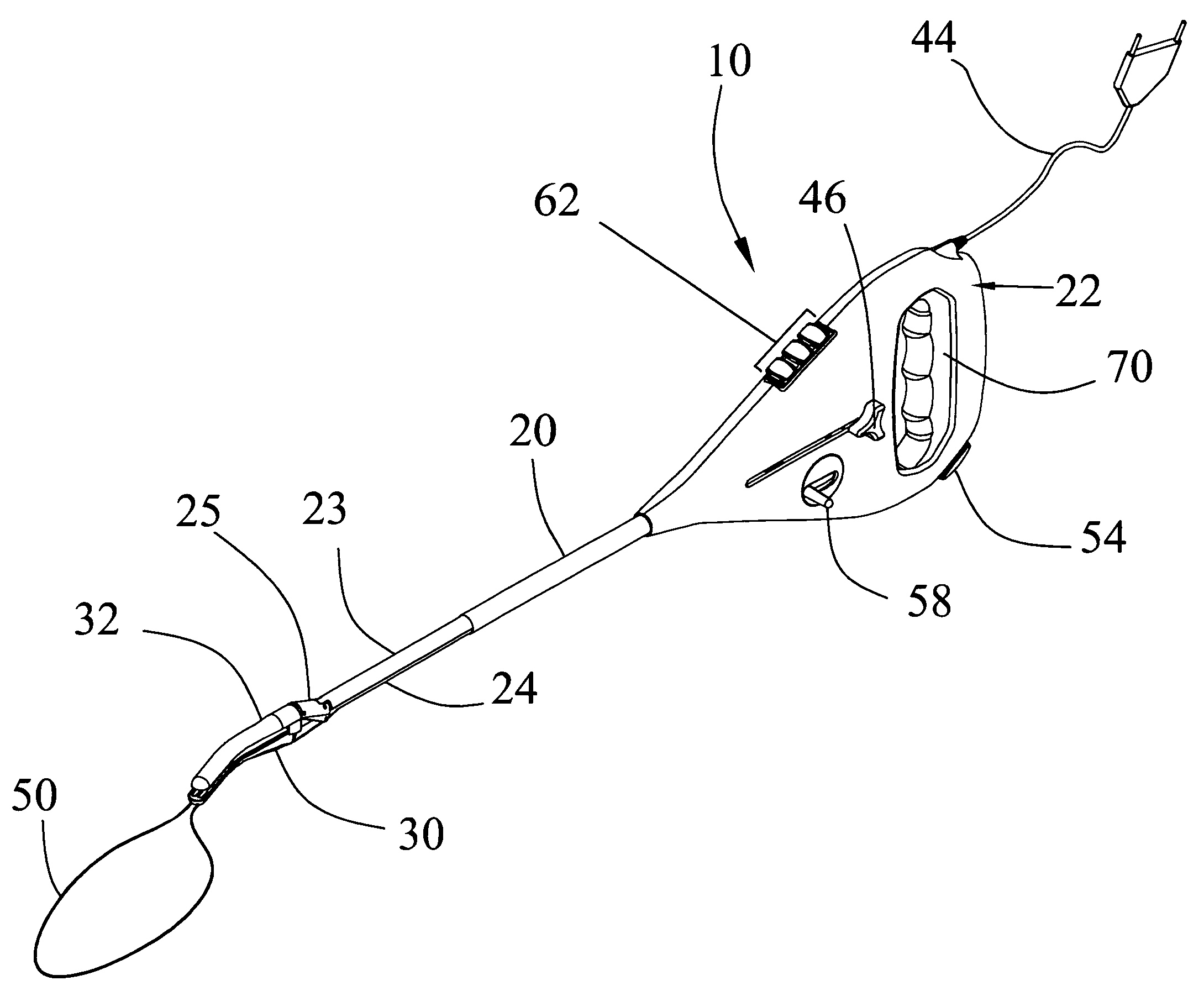
[0013]FIG. 1 is a perspective view of the present invention.

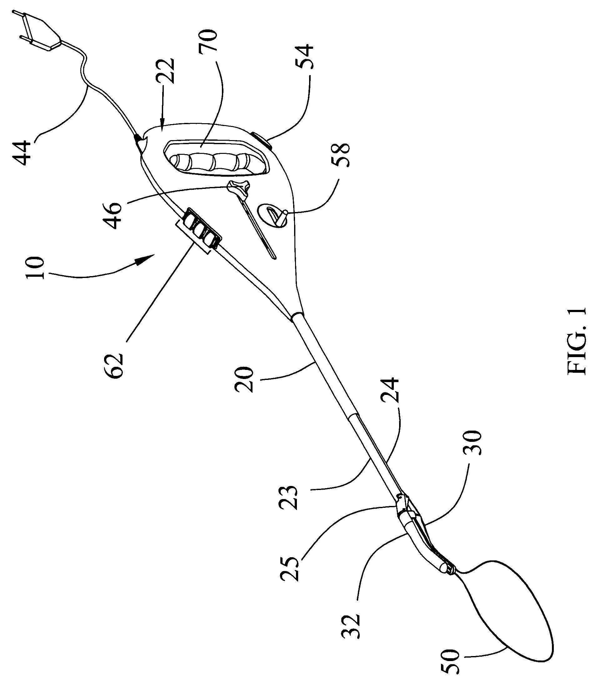
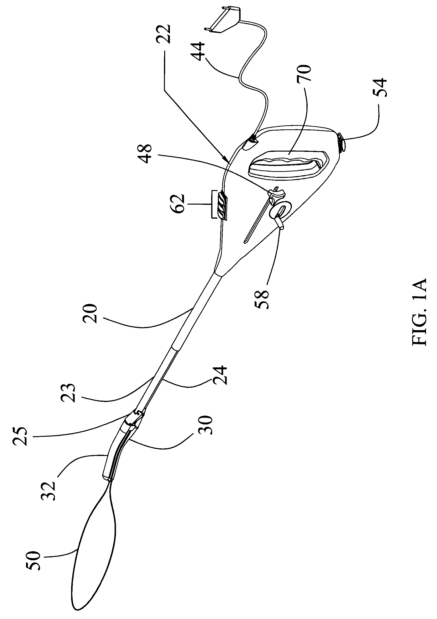
[0014]FIG. 1A is another perspective view of the first embodiment of the present invention.

[0015]FIG. 2 is a detailed view of the internal portions of the handle of the first embodiment.

[0016]FIG. 2A is a detailed, cutaway view of the handle of the first embodiment.

[0017]FIG. 3 is a detailed view of the first embodiment of the jaw members.

[0018]FIG. 3A is another detailed view of the first embodiment of the jaw members.

[0019]FIG. 3B is a cross-sectional view of the link and the jaw members in the first embodiment of the jaw members.

second embodiment

[0020]FIG. 4 is a detailed view of the jaw members in an open position.

[0021]FIG. 4A is a detailed view of the second embodiment of the jaw members in a closed position.

third embodiment

[0022]FIG. 5 is a detailed view of the jaw members in an open position.

[0023]FIG. 5A is a detailed view of the third embodiment of the jaw members in a closed position.


PUM


Abstract

A resecting device is disclosed. The resecting device comprises: a handle having a jaw trigger slidably engaged with the handle and mechanically engaged with a spring mechanism communicating a biasing force to the jaw trigger; a fixed shaft portion having a first and a second end, wherein the fixed shaft portion first end is affixed to the housing, wherein the fixed shaft portion second end forms a first jaw member, and wherein the first jaw member has a tissue contact area; and a slidable shaft portion in communication with the spring mechanism and slidable relative to the fixed shaft portion.

Description

CROSS REFERENCE TO RELATED APPLICATIONS[0001]Applicant claims priority under 35 U.S.C. § 119 (e) of provisional U.S. Patent Application Ser. No. 60,818,847 filed on Jul. 6, 2006, which is incorporated by reference herein.FIELD OF INVENTION[0002]This invention relates to a surgical instrument and, more specifically, to a multi-polar electrosurgical resecting device.STATEMENT REGARDING FEDERALLY SPONSORED RESEARCH OR DEVELOPMENT[0003]No federal funds were used to develop or create the invention disclosed and described in the patent application.REFERENCE TO SEQUENCE LISTING, A TABLE, OR A COMPUTER PROGRAM LISTING COMPACT DISK APPENDIX[0004]Not ApplicableAUTHORIZATION PURSUANT TO 37 C.F.R. §§ 1.171 (d), (c)[0005]A portion of the disclosure of this patent document contains material that is subject to copyright and trademark protection. The copyright owner has no objection to the facsimile reproduction by anyone of the patent document or the patent disclosure, as it appears in the Patent ...

Claims


Application Information

Patent Timeline
Patent Type & Authority Patents(United States)
IPC IPC(8): A61B18/18
CPCA61B18/14A61B18/1445A61B18/1447A61B18/1485A61B2017/2945A61B2018/00916A61B2018/1407A61B2018/1412A61B2018/1432A61B2018/1455
Inventor YATES, LEROY L.
Owner YATES LEROY L
Why Eureka
Try Eureka