DNA-bridged carbon nanotube arrays

a carbon nanotube and array technology, applied in the direction of catalyst activation/preparation, catalyst activation/preparation, metal/metal-oxide/metal-hydroxide catalysts, etc., can solve the problems of poor specificity and reproducibility, long recovery time, and prior art probes

Inactive Publication Date: 2005-10-25
TRUSTEES OF BOSTON COLLEGE THE
View PDF9 Cites 241 Cited by
  • Summary
  • Abstract
  • Description
  • Claims
  • Application Information

AI Technical Summary

Benefits of technology

[0010]The present invention also provides methods for incorporating DNA assemblies synthetically into molecular electronic devices and for measuring their electrical conductivities. Using nanofabrication techniques, three-dimensional CNT arrays capped with gold are constructed on a surface and subsequently functionalized chemically with DNA molecules. The ability to “wire” sequences of synthetically defined composition chemically into nanoelectrodes, enables systematical address, at an unprecedented level of detail, based on the influence of DNA structure, sequence, and length on conduction. The sensor devices of the invention utilize the capability of double-stranded DNA to conduct electricity, provides the means to measure the electrical conductivity, and more importantly, changes in electrical conductivity in short (<100 bp) and specific DNA sequences. Sensors of substantially high sensitivity and portability are therefore obtainable. The ability to measure extremely small changes in electrical conductivity in the sensors of the invention is superior to conventional methods used for detecting DNA sequences employing optical methods, such as by laser confocal fluorescence microscopy, thereby rendering them suited for detection and quantitation of extremely low levels of the target species. Furthermore, the sensors of the invention are adaptable to conventional silicon chip technology, whereby sensing can performed off the chip surface. The extra-surface detection in the sensor devices of the invention is achieved by precise placement of electrically conducting CNTs on lithographically-prepared substrates, wherein electrical connections between pairs of carbon nanotubes is completed by target DNA strands complementary to probe DNA strands that are previously set in place. Electrical connectivity between the CNTs and the DNA molecules is achieved via the directed-assembly of DNA molecules onto gold coated CNT's via thiol linkers. Sensors of the present invention have the ability to detect ultra-low levels of a variety of biologically relevant pathogens in air, soil and water samples, and may be configured as a miniaturized, portable device.
[0019]It is another object of the invention to provide a method for anchoring nucleic acids on a substrate surface and rendering to be electrically conducting, thereby enabling use in molecular electrical circuits.

Problems solved by technology

Other limitations of prior art probes include long recovery times, poor specificity and reproducibility, and their inability to be specifically adapted for detection of a wide range of chemical and biological species.
Biological sensing devices offer the potential for providing high a degree of specificity and good sensitivity, but remain largely unexplored due to technical and chemical issues pertaining to their structure-property characterization.
Although charge transport properties of certain macromolecules such as DNA have been studied, their application as sensors has not been explored.
This may be attributed to the inadequate understanding of the nature of the intrinsic properties of DNA, which has proven difficult to study directly using presently available systems.
Nanotechnological approaches to molecular electronics (“molectronics”) although theoretically feasible for sensor applications on the other hand, has not been practically realized mainly because they require materials with programmable structural and electronic characteristics.

Method used


Image

  • DNA-bridged carbon nanotube arrays
  • DNA-bridged carbon nanotube arrays
  • DNA-bridged carbon nanotube arrays

Examples


example 1

Controllable Creation of Arrays of Addressable Multi-walled Carbon Nanotubes

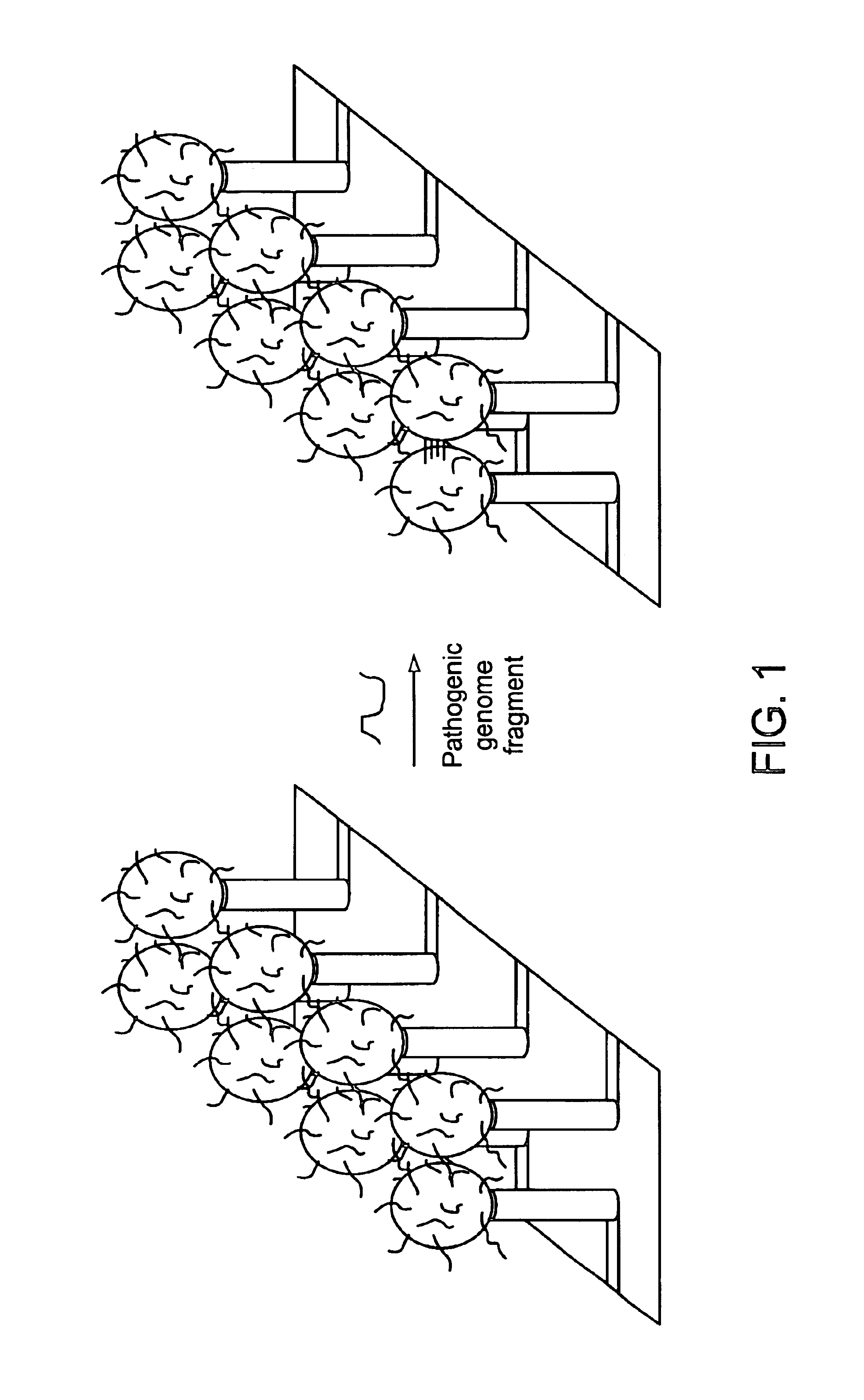
[0086]CNTs are grown by the plasma-enhanced hot filament chemical vapor deposition method, including on an e-beam patterned substrate. Metallic nickel, deposited via e-beam lithography over a non-catalytic metal provides the electrical leads, is used as the catalyst for CNT growth.

example 2

Growth of Controlled Dimension Gold-coated Spheres

[0087]Gold-coating procedure of spheres utilizes the functionalization of microspheres with thiols groups to enable the self-assembly of metallic gold nanoparticles on functionalized sphere surfaces. The initially formed gold layer is subsequently built up either through sequential steps of linker addition followed by additional contact with gold nanoparticles, or through electroless deposition of gold on the functionalized sphere surfaces.

example 3

Synthesis of DNA Sequences with Thiol Linkers

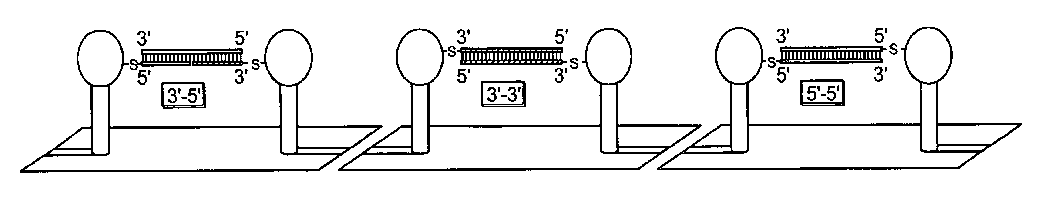
[0088]The synthetic method involves a solution-phase reaction between 4-mercaptobenzoic acid and a terminal amine either at the 2′ or 5′ position on the ribose moiety. The incorporation of an amine at the 2′ or 5′ position is accomplished during chemical DNA synthesis using commercially available reagents. A 2′-derivatization is carried out to orient the DNA away from a gold surface when the linker is placed at the 3′ end of an oligonucelotide, while a 5′-derivization is done to orient the oligonucleotide linked at the 5′ end. Alternatively 4-mercaptobenzoic acid is reacted with a 5′ pendant alkyl-amine or the incorporation of a short alkanethiol linker to the 3′ end of DNA using a commercially-available reagent.


PUM

PropertyMeasurementUnit
thicknessaaaaaaaaaa
heightaaaaaaaaaa
diameteraaaaaaaaaa

Abstract

A class of biological sensing devices that include a substrate comprising an array of carbon nanotubes (CNTs) to which are chemically attached biological molecules is disclosed. The attached biological molecules are capable of electrical conductivity that is responsive to chemical changes occurring as a result of their interaction with target species. A means for means for using DNA as a material of potential in molecular electronic sensor devices, being primarily based on molecular electron-transfer reaction processes between DNA-binding donors and acceptors is also disclosed, including composition, method of manufacture and their use are described.

Description

[0001]This application claims priority to Provisional U.S. Application Ser. No. 60 / 260,758 filed on Jan. 10, 2001.FIELD OF THE INVENTION[0002]The present invention relates to carbon nanotube devices. More particularly, it relates to carbon nanotube chemical and biological sensor devices.BACKGROUND OF THE INVENTION[0003]The ability to detect chemical and biological species rapidly with specificity and at very low concentrations is becoming increasingly important, particularly in the medical, environmental and forensic areas Detection of low levels pathogenic species such as agents that pose a biological threat, for example, provides a crucial measure of environmental contamination by such agents since their existence, even at low concentrations, can have serious pathological consequences. Sensitive detection devices therefore, enables the elimination of such pathogens prior to their causing significant harm. There is also a growing need for the rapid and quantitative detection of bio...

Claims


Application Information

Patent Timeline
Patent Type & Authority Patents(United States)
IPC IPC(8): B01J23/75B01J23/755B01J37/34B01J37/00C01B31/02C07B61/00C12Q1/68C12Q1/6825C40B40/06C40B60/14G01N33/543G01N33/553
CPCB01J23/75B01J23/755B01J37/341B01J37/344B82Y30/00B82Y40/00C01B31/0233G01N33/5438G01N33/54393G01N33/553B01J2219/00432B01J2219/00527B01J2219/00605B01J2219/00612B01J2219/00621B01J2219/0063B01J2219/00637B01J2219/00648B01J2219/00659B01J2219/00664B01J2219/00677B01J2219/00722C12Q1/6825C40B40/06C40B60/14Y10S977/958C01B32/162C12Q2563/116C12Q2565/519C12Q2565/607
Inventor KELLEY, SHANA O.FOURKAS, JOHNNAUGHTON, MICHAELREN, ZHIFENG
Owner TRUSTEES OF BOSTON COLLEGE THE
Why Eureka
Try Eureka