Telemetry method and apparatus using magnetically-driven MEMS resonant structure

a technology of magnetic resonance and telemetry, applied in the field of telemetry methods and apparatus using magnetic resonance resonant structure, can solve the problems of clinical diagnosis, based on infrequent testing, optic nerve damage and blindness, and unique problems of measuring physiological parameters within a living body, and achieve the effects of improving reliability and ease-of-use of sensors, high quality factor (q), and high sensitivity

Inactive Publication Date: 2007-10-11
LAUNCHPOINT TECH
View PDF1 Cites 281 Cited by
  • Summary
  • Abstract
  • Description
  • Claims
  • Application Information

AI Technical Summary

Benefits of technology

[0023] An advantage of the present invention is the high quality factor (Q) that is attainable with mechanical resonant structures relative to LC resonant circuits and the improved reliability and ease-of-use of a sensor based on a high-Q resonator. Further, magnetic couplings allow for communication with the sensor through biological tissues. The resonant structure includes a magnetic material and is adapted to vibrate in response to a time-varying magnetic field. The apparatus also includes a receiver to measure a plurality of successive values magnetic field emission of the vibrating structure taken over an operating range of successive interrogation frequencies to identify a resonant frequency value for said sensor.
[0024] Another aspect of the present invention is to provide a pressure sensing apparatus for operative arrangement within an environment that incorporates a resonant structure with at least one magnetically-driven resonant beam that will vibrate in response to a time-varying magnetic field (whether radiated continuously over an interval of time or transmitted as a pulse). The resonant beam may be enclosed within a hermetically-sealed diaphragm, at least one side of the diaphragm having a flexible membrane to which the resonant structure is coupled. The pressure sensing apparatus also includes a receiver unit capable of picking up emissions (whether electromagnetic or acoustic) from the sensor. Preferably, the receiver (a) measures a plurality of successive values of coil resistance corresponding to the frequency of the sensor taken over an operating range of successive interrogation frequencies to identify a resonant frequency value for the sensor, or (b) detects a transitory time-response of resonance intensity of the sensor due to a time-varying magnetic field pulse to identify a resonant frequency value thereof. In the latter case, the detection can be done after a threshold amplitude value for the transitory time-response of residence intensity has been observed; then a Fourier transform can be performed on the transitory time-response of the emission to convert the detected time-response information into the frequency domain.
[0025] It is an aspect of the present invention to provide a sensing apparatus for measuring quantities convertible from changes in physical observations, the apparatus including: a resonant structure responsive to the changes in the physical observations, the resonant structure including a magnetized element; an electromagnetic coil operationally coupled to the magnetized element, the electromagnetic coil being an excitation coil magnetically coupled to the magnetized element to excite a resonance of the resonant structure; and, a signal processor for processing movement of the resonant structure, the signal processor correlating the movement with regard to the changes in the physical observations so as to produce sensed data. The resonant structure includes: a substrate locatable in an environment to be monitored, a flexible diaphragm hermetically sealed to the substrate and in communication with the environment to be monitored, a sealed chamber encompassed by the substrate and the at least one flexible diaphragm, and a resonant beam connected to the magnetized element, the resonant beam suspended within the sealed chamber and mechanically coupled to the flexible diaphragm, wherein the magnetized element oscillates the resonant beam in response to an electromagnetic signal generated by the signal processor and formed by the electromagnetic coil.
[0026] It is another aspect of the present invention to provide a method of sensing physical observations within an environment, the method including: operatively arranging a resonant structure in the environment and in proximity to a direct current bias field, the resonant structure including a magnetized element and being responsive to changes in the physical observations; applying a magnetic field by way of an electromagnetic coil operationally coupled to the magnetized element; measuring a plurality of successive values for magnetic resonance intensity of the resonant structure with a signal processor operating over a range of successive interrogation frequencies to identify a resonant frequency value of the resonant structure; and using the resonant frequency value to identify sensed data correlating to the physical observation of the environment.
[0027] Many advantages exist by providing the flexible new pressure sensing apparatus of the invention and associated new method of sensing pressure of an environment using a sensor with at least one magnetically-driven resonant structure. Such advantages include, but are not limited to, the following:
[0028] (a) Sensitivity—The method provides a means for achieving high sensitivity and high-Q resonance frequency.

Problems solved by technology

Within the field of biomedical devices, the measurement of physiological parameters within a living body presents unique problems.
Glaucoma is a serious disease that can cause optic nerve damage and blindness.
Moreover, eye pressure can vary throughout the day such that clinical diagnosis, based on infrequent testing, is often delayed.
While this method is cost effective, it suffers from a number of significant drawbacks.
For example, a trained clinician is required for the measurement so that frequent monitoring is not possible.
Further, the mechanical properties of the cornea can affect the measurement.
However, such devices were not sufficiently compact and reliable for clinical use in humans, and lacked a method of implantation and attachment.
Moreover, LC resonant sensors fail to provide a sufficiently sharp resonance to allow for rapid and simple external sensing of frequency and hence pressure.
However, the problems of low Q associated with resistive losses in the coil and other conductors remained due to sensitivity of such system to the relative position of the sensor and the inductive pick-up coil.
The relatively high intensity light requirements may interfere with the patient's vision or may otherwise not likely be suitable for use near the human eye.
While applications for wireless sensors located in a stent have been suggested, no solution exists to the difficulty in fabricating a pressure sensor with telemetry means sufficiently small enough for incorporation into a stent.
In nearly all of the aforementioned cases, the disclosed devices require a complex electromechanical assembly with many dissimilar materials.
This typically results in significant temperature and aging-induced drift over time.
Such assemblies may also be too large for many desirable applications—e.g., including intraocular pressure monitoring and / or pediatric applications.
Finally, complex assembly processes make such devices prohibitively expensive to manufacture for widespread use.
Such manufacturing complexity only increases with alternative process that form microfabricated sensors which have recently been proposed as an alternative to conventionally fabricated devices.
While magneto-mechanical pressure sensors have advantages such as high operating reliability and low manufacturing cost over previous electromagnetic markers of high sensitivity, there are known problems associated with such a pressure sensor.
Consequently, such magnetostrictive pressure sensors often require independent temperature correction that involves the use of additional temperature and measurement devices that add size and preclude construction as a single monolithic structure or adaptation to a micro-miniature size suitable for monitoring physiological parameters.
A possible disadvantage is that any parasitic coupling between the drive and sense electrodes may diminish accuracy of the resonant gauge.
Furthermore, in a conventional capacitive drive arrangement, the force between the oscillating beam and drive electrode is quadratic, resulting in an unwanted frequency pulling effect.
While crystalline quartz piezoresistors have been satisfactorily employed in resonant gauge applications, their size limits their practical utility.
Although these devices have considerable advantages, such as, for example, high accuracy and stability of measurement even for very wide measurement ranges (up to several hundred bars), such known sensors suffer from some drawbacks.
In particular, calibration is fairly complicated and manufacture is not an easy task, producing fairly high rejection rates of the finished products.
However, such cantilevers and micro-compasses fail to provide a solution in measuring other quantities convertible to measuring changes in mechanical stress (i.e., pressure and force).

Method used


Image

  • Telemetry method and apparatus using magnetically-driven MEMS resonant structure
  • Telemetry method and apparatus using magnetically-driven MEMS resonant structure
  • Telemetry method and apparatus using magnetically-driven MEMS resonant structure

Examples


Embodiment Construction

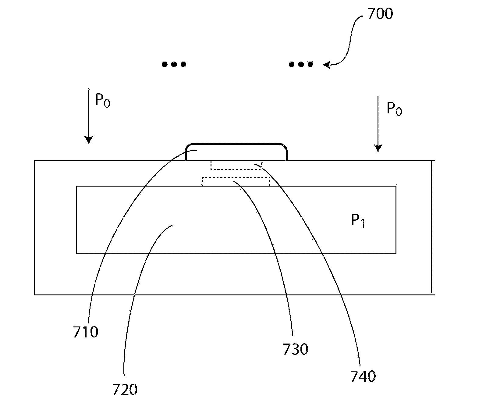
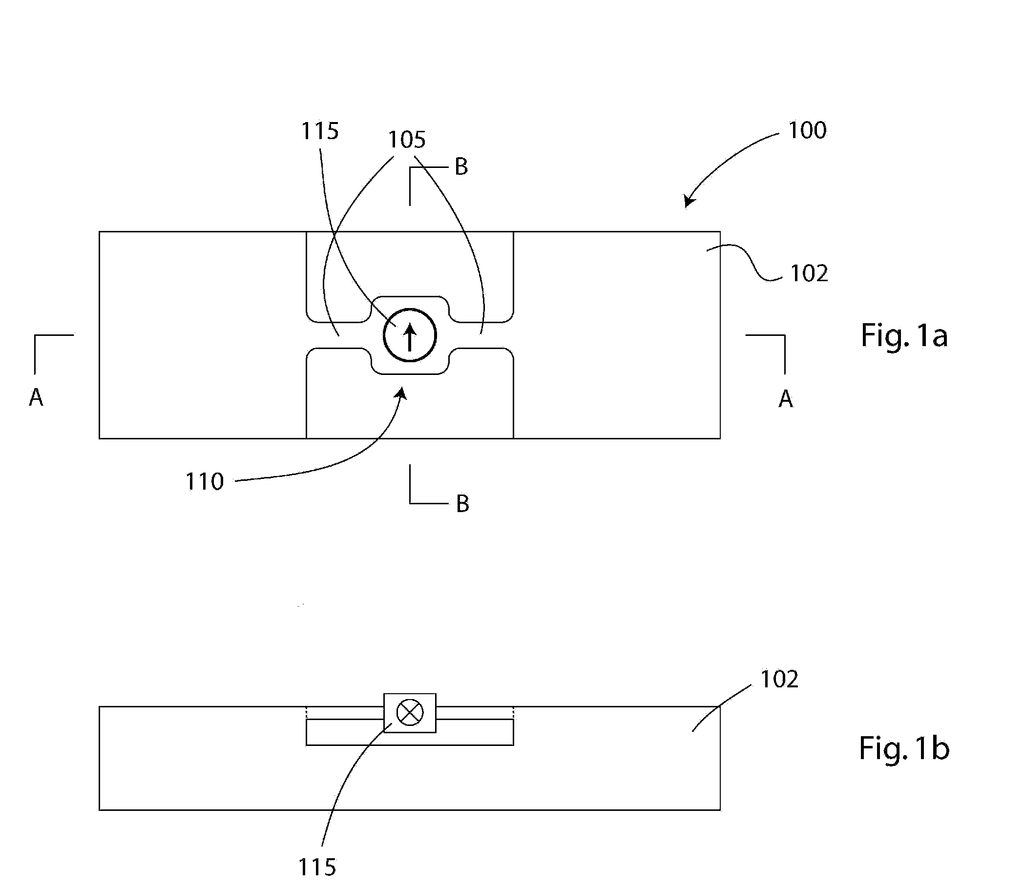
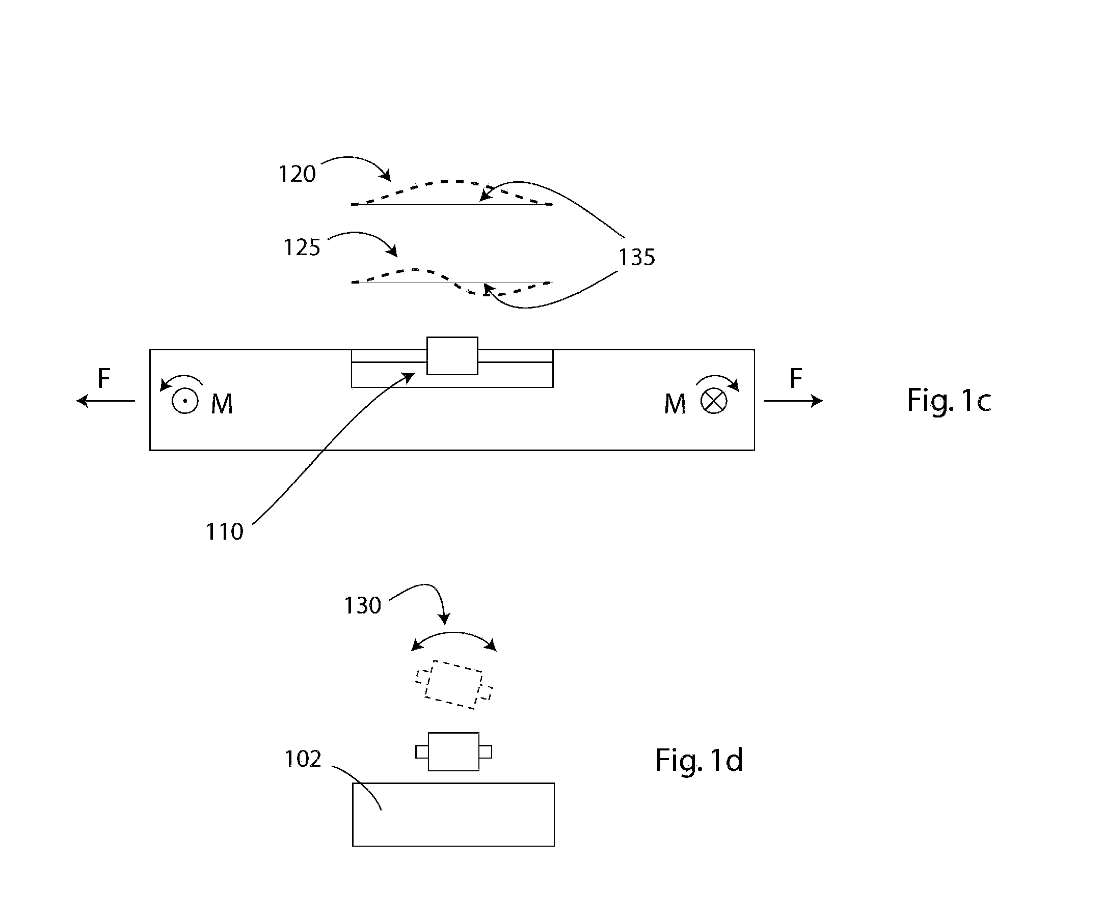
[0082] Generally, the present invention provides a method and apparatus including a magnetically-driven resonant structure suitable for measuring some change in a physical observation—e.g., sensing change in pressure, flow, etc. However, for purposes of illustration, the present invention is discussed in terms of a method and apparatus suitable for measuring intraocular pressure in patients having glaucoma or patients at risk of contracting the disease and having intraocular lenses (IOL's). As discussed earlier, previous devices fail to meet dimensional requirements, or they suffer from sensitivity limitations needed for wireless physiologic parameter measurement within a living body.

[0083] Before explaining the present invention in detail, it should be noted that the invention is not limited in its application or use to the details of construction and arrangement of parts illustrated in the accompanying drawings and description. The illustrative embodiments of the invention may be...


PUM


Abstract

A telemetry method and apparatus using pressure sensing elements remotely located from associated pick-up, and processing units for the sensing and monitoring of pressure within an environment. This includes remote pressure sensing apparatus incorporating a magnetically-driven resonator being hermetically-sealed within an encapsulating shell or diaphragm and associated new method of sensing pressure. The resonant structure of the magnetically-driven resonator is suitable for measuring quantities convertible to changes in mechanical stress or mass. The resonant structure can be integrated into pressure sensors, adsorbed mass sensors, strain sensors, and the like. The apparatus and method provide information by utilizing, or listening for, the residence frequency of the oscillating resonator. The resonant structure listening frequencies of greatest interest are those at the mechanical structure's fundamental or harmonic resonant frequency. The apparatus is operable within a wide range of environments for remote one-time, random, periodic, or continuous/on-going monitoring of a particular fluid environment. Applications include biomedical applications such as measuring intraocular pressure, blood pressure, and intracranial pressure sensing.

Description

CROSS REFERENCE TO RELATED APPLICATIONS [0001] This application claims does not claim any benefit of priority. STATEMENT OF FEDERALLY SPONSORED RESEARCH OR DEVELOPMENT [0002] This application is not currently the subject of any U.S. Government sponsored research or development. FIELD OF THE INVENTION [0003] The present invention relates generally to an apparatus including a resonant structure suitable for measuring quantities convertible to mechanical stress or mass in the resonant structure and a related method. More particularly, the present invention relates to an apparatus and method including a magnetically-driven resonant sensor suitable for wireless physiological parameter measurement and telemetry within a living body. BACKGROUND OF THE INVENTION [0004] Within the field of biomedical devices, the measurement of physiological parameters within a living body presents unique problems. Such problems and related known solutions can be found, for example, in the treatment of glauc...

Claims


Application Information

Patent Timeline
Patent Type & Authority Applications(United States)
IPC IPC(8): A61B5/05G01R33/12
CPCA61B3/16
Inventor PADEN, BRADLEY E.NORLING, BRIANVERKAIK, JOSIAH E.
Owner LAUNCHPOINT TECH
Why Eureka
Try Eureka