Apparatus for the deposition of high dielectric constant films

a dielectric constant film and apparatus technology, applied in chemical vapor deposition coatings, coatings, metallic material coating processes, etc., can solve the problems of reducing the vapor temperature control of the gate, and reducing the vapor temperature control accuracy. , to achieve the effect of improving vapor temperature control

Inactive Publication Date: 2006-09-07
APPLIED MATERIALS INC
View PDF20 Cites 266 Cited by
  • Summary
  • Abstract
  • Description
  • Claims
  • Application Information

AI Technical Summary

Benefits of technology

[0017] This invention provides an apparatus for depositing a film, particularly a High k film. To deliver High k films better, an embodiment of the apparatus has a shortened vapor delivery system in which the conduits from the vapor delivery system to the processing region are segmented into multiple individually heated and controlled sections that allow precise vapor temperature control. Additionally, an embodiment of the apparatus segments the gas and liquid delivery systems into separate but similar individually heated and controlled sections to improve vapor temperature control. Further, an embodiment of the apparatus segments the chamber assembly into individually controlled sections that are heated to allow more precise vapor temperature control, to reduce vapor deposition on the chamber itself, and to reduce chamber assembly temperature where warranted. Additionally, an embodiment of the invention allows for the simultaneous delivery of two separate High k sources, thus allowing for multi-component film deposition.

Problems solved by technology

As the dimensions of the transistors continue to decrease, the continued use of silicon dioxide as a dielectric gate material is problematic.
The fundamental problem is the need to keep the capacitance of the gate high while the area of the gate is shrinking faster than the thickness of the gate dielectric stack.
But, as the SiO2 thickness approaches 1 nanometer, the leakage-current density approaches an unacceptable 100 A / cm2 at the same operating voltage.
The material selected for the dielectric film effects the mobility of the carriers in the transistor channel, thereby affecting overall transistor performance.
As a result of the vast difference in vapor pressure illustrated by TAETO and TEOS, prior art vapor delivery systems do not encounter and do not provide solutions to many of the challenges resulting from the use of very low vapor pressure precursors such as TAETO and TAT-DMAE.
Such a configuration, when used with low vapor pressure tantalum precursors, can lead to problems stabilizing the tantalum vapor output and difficulty achieving the constant, repeatable tantalum vapor output desired in semiconductor device fabrication.
Positioning the vaporizer and flow meter according to prior art systems fails to adequately control precursor vapor in the case of low vapor pressure precursors.
Purging techniques such as these fail with tantalum systems because the residual tantalum precursor has such a low vapor pressure that to remove it a system must introduce a solvent, such as isopropyl alcohol, ethanol, hexane, or methanol, into both the vaporization system and supply lines.
Unfortunately, since the object of these large scale temperature control systems is to heat and monitor an average temperature of a large section of piping, these systems lack the ability to specifically control a single, smaller section of the vapor piping.
An additional detriment is that these systems generally have very low efficiency when higher line temperatures are desired.
Minimizing the length of lines requiring heating not only reduces the overall system complexity but also decreases the footprint or overall size of the system.
Current methods of tantalum oxide deposition use reaction rate limited chemical vapor deposition techniques.
Existing chemical vapor deposition reactors do not sufficiently address the thermal losses from the substrate onto which the tantalum film is to be formed and the internal chamber components such as the gas distribution showerhead.
Such thermal losses result in a non-uniform thickness of deposited tantalum and this non-uniformity is one barrier to having commercially viable tantalum oxide film formation techniques.

Method used


Image

  • Apparatus for the deposition of high dielectric constant films
  • Apparatus for the deposition of high dielectric constant films
  • Apparatus for the deposition of high dielectric constant films

Examples


Embodiment Construction

[0052] The foregoing and other aspects and advantages will be better understood from the following detailed description of the preferred embodiments of the invention with reference to the drawings. Like reference numerals refer to corresponding parts throughout the drawings.

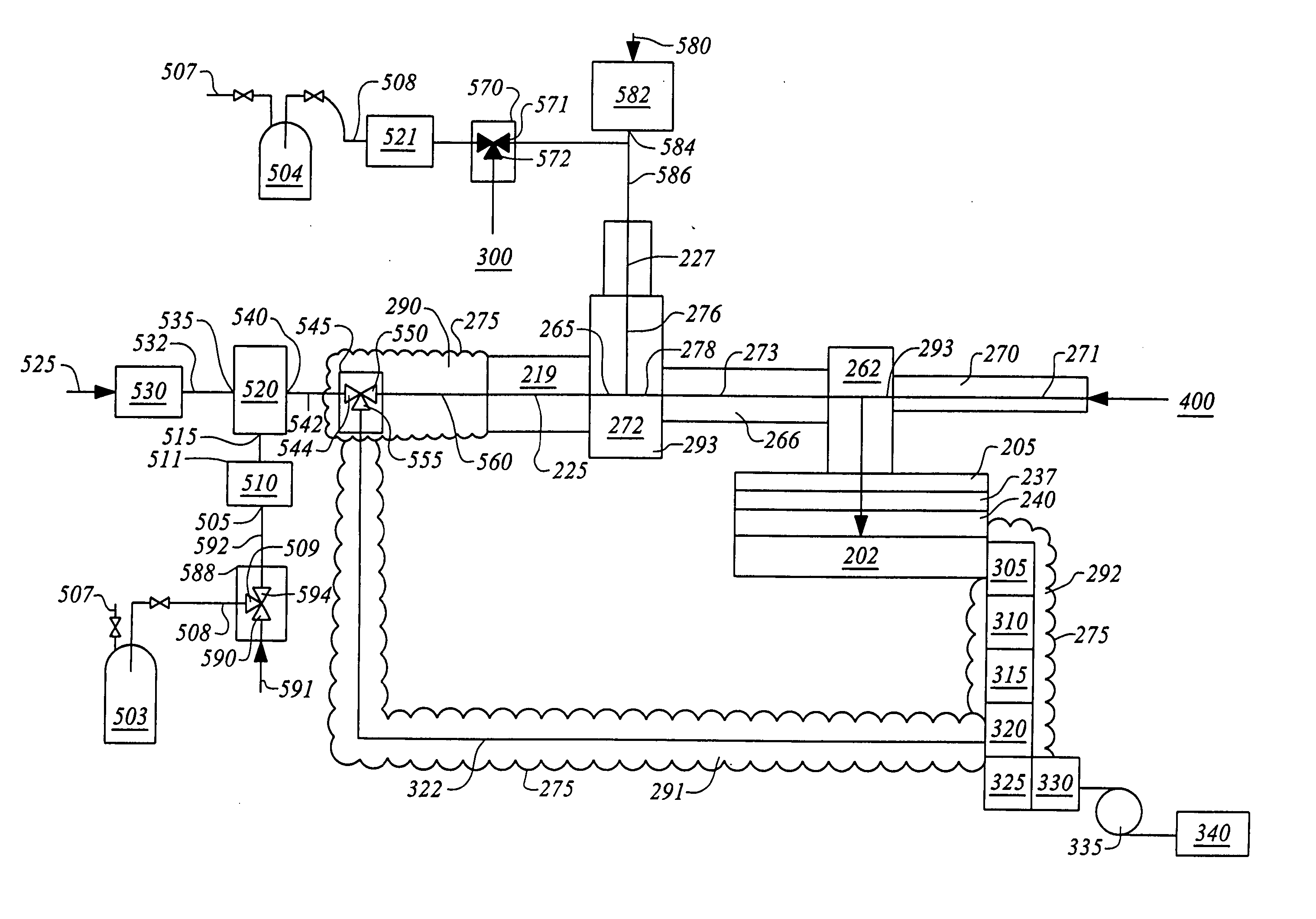
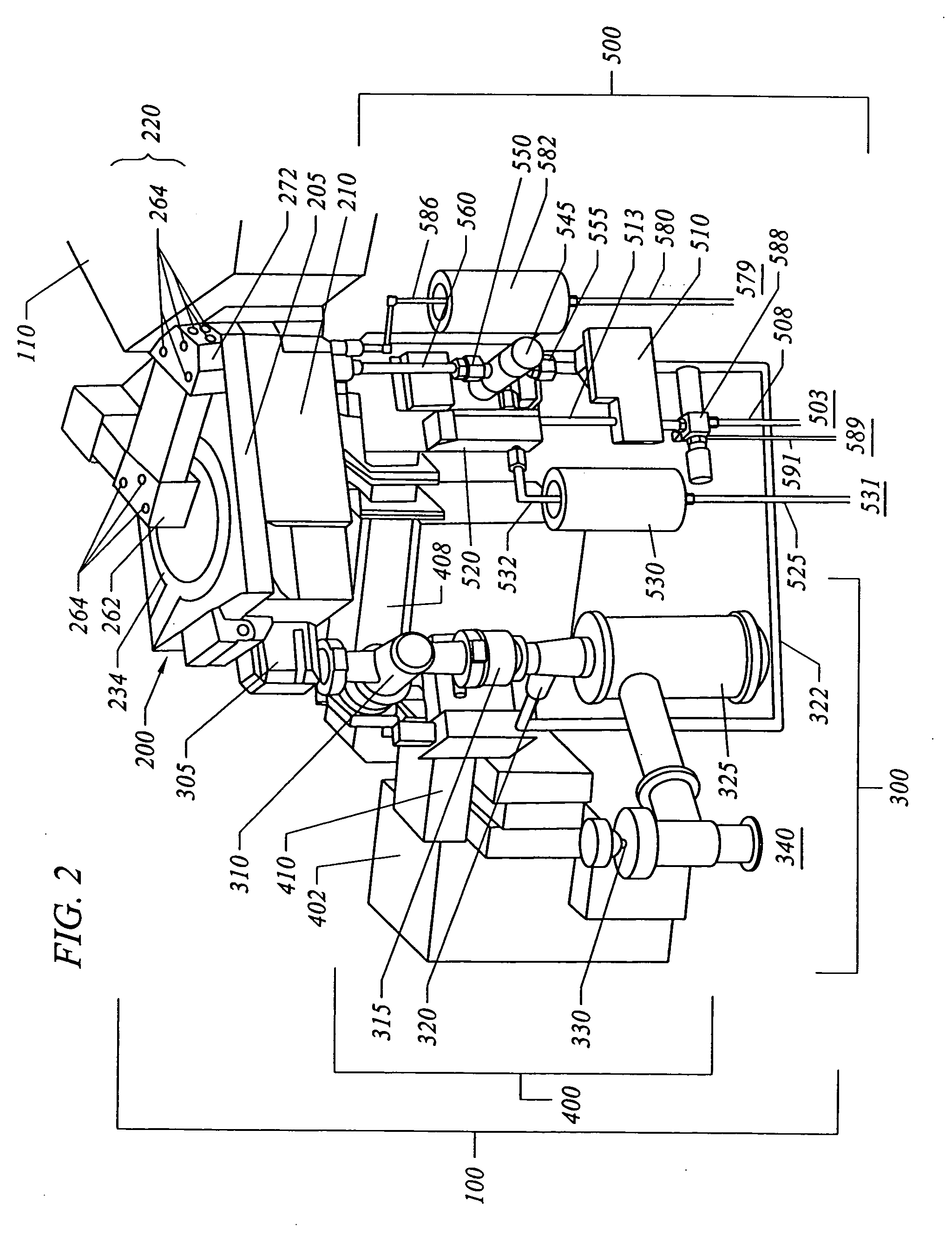
[0053] The present invention is directed to a novel liquid delivery system (LDS), chemical vapor deposition (CVD) chamber, exhaust system, and remote plasma generator that together comprise a unique system especially useful for depositing thin metal-oxide films, such as hafnium silicate, as well as other films requiring vaporization of low volatility precursor liquids. This system also provides for an in-situ cleaning process that removes the metal-oxide films that are deposited on the interior surfaces of a deposition chamber as a by-product of the deposition process. The system also has application in making ultra large scale integration (ULSI) DRAM and other advanced electronic devices that require the deposi...


PUM

PropertyMeasurementUnit
temperatureaaaaaaaaaa

Abstract

An integrated deposition system is described that is capable of vaporizing low vapor pressure liquid precursors and conveying the vapor to a processing region to fabricate advanced integrated circuits. The integrated deposition system includes a heated exhaust system, a remote plasma generator, a processing chamber, a liquid delivery system, and a computer control module that together create a commercially viable and production worthy system for depositing high capacity dielectric materials from low vapor pressure precursors.

Description

CROSS-REFERENCE TO RELATED APPLICATIONS [0001] This application is a continuation of U.S. application Ser. No. 10 / 251,715, filed Sep. 20, 2002, which is a continuation-in-part of U.S. Pat. No. 6,454,860, both of which are incorporated by reference in their entireties.BACKGROUND OF THE INVENTION [0002] 1. Field of the Invention [0003] The invention relates to an apparatus for the vaporization of liquid precursors and the controlled delivery of those precursors to form films on suitable substrates. More specifically, this invention concerns an apparatus for the deposition of a high dielectric constant film on a silicon wafer to make integrated circuits useful in the manufacture of advanced dynamic random access memory modules and other semiconductor devices. [0004] 2. Description of the Related Art [0005] As the dimensions of the transistors continue to decrease, the continued use of silicon dioxide as a dielectric gate material is problematic. The fundamental problem is the need to k...

Claims


Application Information

Patent Timeline
Patent Type & Authority Applications(United States)
IPC IPC(8): C23C16/00C23C16/40C23C16/44C23C16/448C23C16/452C23C16/455C23C16/54
CPCC23C16/407C23C16/44C23C16/4401C23C16/4405C23C16/4411C23C16/4412C23C16/448C23C16/4481C23C16/452C23C16/45561C23C16/45565C23C16/4557C23C16/4586C23C16/54H01L21/6719H01L21/02271H01L21/18H01L21/20H01L21/31C23C16/4409
Inventor RONSSE, BOBBY M.METZNER, CRAIG R.COLLINS, RICHARD OMAR
Owner APPLIED MATERIALS INC
Why Eureka
Try Eureka