Gas-sensitive sensor calibration and reliability testing system

A technology of gas sensor and test system, which is applied in the direction of instruments, measuring devices, scientific instruments, etc., to achieve the effect of device temperature

Inactive Publication Date: 2008-08-13
INST OF MICROELECTRONICS CHINESE ACAD OF SCI
View PDF0 Cites 39 Cited by
  • Summary
  • Abstract
  • Description
  • Claims
  • Application Information

AI Technical Summary

Problems solved by technology

[0007] In view of this, the main purpose of the present invention is to provide a gas sensor calibration and reliability testing system to solve the shortcomings of the existing dynamic gas sensor performance testing device, to achieve precise control of the gas concentration to be measured, Test of different gases, and precise control of device temperature

Method used


Image

  • Gas-sensitive sensor calibration and reliability testing system
  • Gas-sensitive sensor calibration and reliability testing system
  • Gas-sensitive sensor calibration and reliability testing system

Examples


Embodiment Construction

[0037] In order to make the objectives, technical solutions, and advantages of the present invention clearer, the following further describes the present invention in detail in conjunction with specific embodiments and with reference to the accompanying drawings.

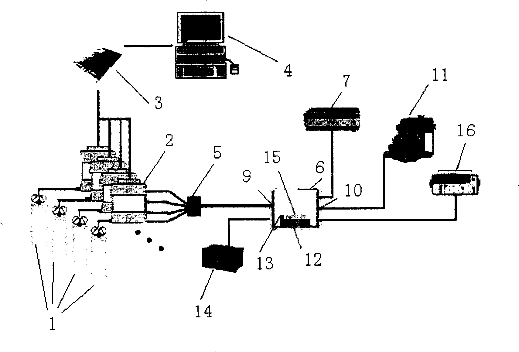
[0038] Such as figure 2 As shown, figure 2 It is a schematic diagram of the structure of the gas sensor calibration and reliability test system provided by the present invention. The system includes an air inlet unit, a gas flow monitoring and component control unit, a gas mixing chamber 5, a vacuum test chamber 6 and a sensor electrical parameter measuring device 16 .

[0039] The gas in the air inlet unit enters the gas mixing chamber 5 for premixing under the control of the gas flow monitoring and composition control unit, and then enters the vacuum test chamber 6.

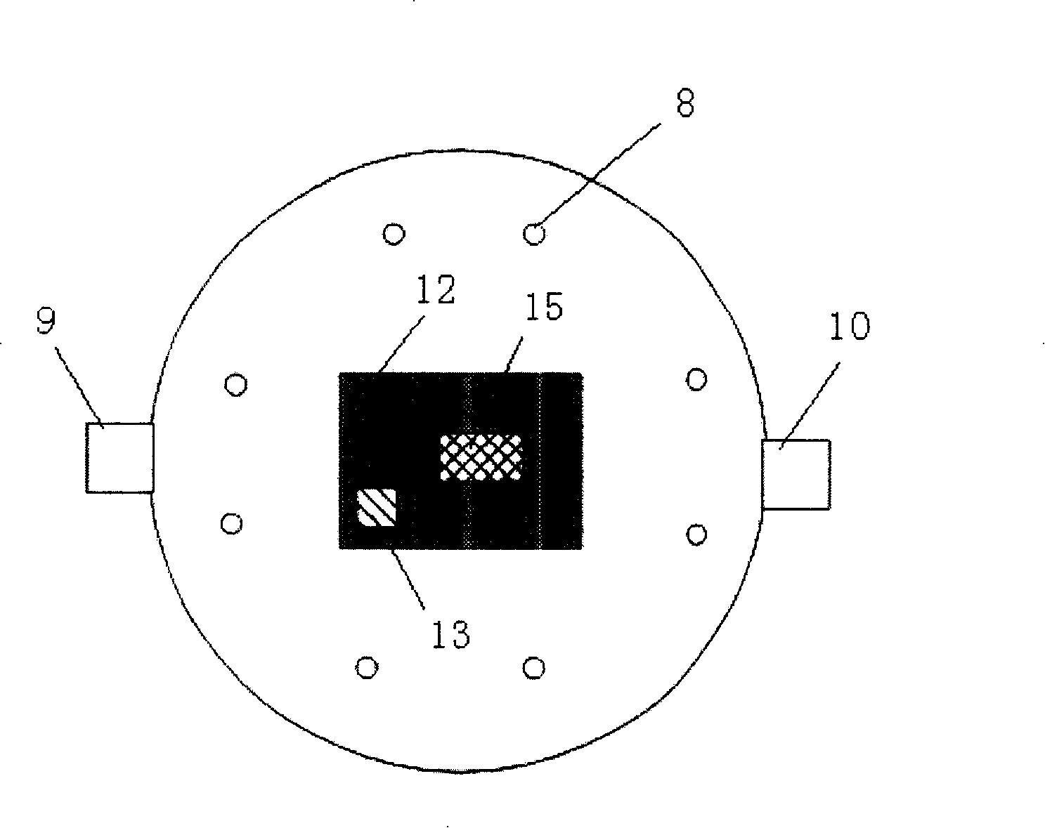
[0040] A gas sensor 15 to be tested is placed in the vacuum test cavity 6, and the sensor electrical parameter measuring device 16 is connected to the...


PUM

PropertyMeasurementUnit
heightaaaaaaaaaa
diameteraaaaaaaaaa

Abstract

The invention relates to the field of testing technique of gas sensor and discloses a system for testing calibration and reliability of gas sensor. The system comprises of inlet unit, gas flow monitor, components control unit, gas mixed cavity, vacuum testing cavity and sensor electric parameter measuring device. Gas in said inlet unit is entered in gas mixed cavity to premix under the control of gas flow monitor and components control unit, and then to vacuum testing cavity which has gas sensor to be determined, the said sensor electric parameter measuring device is connected with vacuum testing cavity to detect capacity of gas sensor to be determined in vacuum testing cavity. The present invention avoids the disadvantages of dynamic gas elements capacity testing device in existence, realizes controlling exactly consistence of gas to be measured, testing different gas and controlling exactly temperature of elements.

Description

Technical field [0001] The invention relates to the technical field of gas sensor testing, in particular to a gas sensor calibration and reliability test system with fast response speed and precise and controllable gas concentration to be measured. Background technique [0002] The early gas sensor test system used a closed intake system, and its main feature was to directly inject the target test gas into the closed sensor chamber. This type of test system can only be used to measure the steady-state response of the sensor. Moreover, due to the limitation of the diffusion speed of the gas to be measured in the carrier gas, the time for the sensor to reach a steady-state response becomes longer, and after the sensor adsorbs the gas, the desorption speed is relatively slow, which is not suitable for a large number of sample data collection. [0003] In order to obtain the dynamic response characteristics of the gas sensor, a flow-gas test system is required. At present, the struct...

Claims


Application Information

Patent Timeline
Patent Type & Authority Applications(China)
IPC IPC(8): G01N27/00
Inventor 黄钦文陈大鹏景玉鹏欧毅叶甜春
Owner INST OF MICROELECTRONICS CHINESE ACAD OF SCI
Why Eureka
Try Eureka