Catheter with cryogenic and heating ablation

a technology of cryogenic and heating ablation, which is applied in the field of cryogenic catheters and wands, can solve the problems of applying destructive thermal extremes to adjacent tissues, and achieve the effects of reducing time or movement sequence, reducing tip temperature, and facilitating operation

Inactive Publication Date: 2006-08-29
MEDTRONIC CRYOCATH LP
View PDF66 Cites 243 Cited by
  • Summary
  • Abstract
  • Description
  • Claims
  • Application Information

AI Technical Summary

Benefits of technology

[0011]One or more of these and other desirable features are achieved in a catheter that includes a treatment segment with both heating and cryoablation elements and a controller that operates both these sets of elements to control the extent of the ablation lesion. The catheter may, for example, be a modified phase-change cryocatheter with a tip through which a controllably injected phase change coolant circulates to lower the tip temperature, and also possessing an RF electrode assembly. The cryogenic and RF supplies are operated in coordination to set a tip environment or to condition the tissue, also applying a destructive thermal extreme in the adjacent tissue. Starting from a set tip temperature and initial time interval, which may for example condition the surrounding tissue, a controller operates one or both tip energy sources to ablate the tissue. The RF electrode may be operated to affect the depth or location of a lesion, or to thaw cryogenically-cooled tissue, and / or to reduce the time or movement sequence between successive ablations. Similarly, the coolant may be controlled to chill the tissue prior to or during an RF ablation or warming treatment regimen, allowing greater versatility of operation and enhancing the speed or placement lesions in a treatment cycle. In one electrical embodiment, the electrode is configured for applying microwave energy to penetrate and undergo preferential absorption beyond, an ice boundary, thus extending the depth or range of a cryoablation treatment target region. In another embodiment, the cooling and application of RF energy are controlled to balance energy flux in the near field while heating (or cooling) the far field so as to position an ablation region away from the surface contacted by the electrode. The driver or RF energy source may supply microwave energy at a level effective to prevent ice formation in the near field yet deliver a cumulatively destructive level of heating at depth, or it may be configured to apply microwave-band energy after initial freezing, at a frequency effective to penetrate the ice ball which develops on a cryocatheter, and with an absorption coefficient effective to form an ablation layer of defined thickness that either extends to, or starts at a defined distance or depth. The controller may also select a thermal set point to initiate or to carry out treatment for different tissue applications at a temperature between 70 and minus 70 degrees Celsius, so that a temporally offset thermal conduction profile is applied to an RF heating profile. For example, the cryogenic segment may be operated to pre-chill adjacent tissue before RF ablation commences, so as to permit the RF energy to be applied for a longer time without prematurely or excessively denaturing the tissue near the electrode. When operating with microwave energy through a cryogenic ice ball, the catheter may extend the depth and width of the region of active ablation, allowing a small endovascular catheter to create larger ablations in a controlled manner. The cryocatheter may be fitted with a bipolar RF ablation electrode assembly positioned to facilitate lesion placement.

Problems solved by technology

The cryogenic and RF supplies are operated in coordination to set a tip environment or to condition the tissue, also applying a destructive thermal extreme in the adjacent tissue.

Method used


Image

  • Catheter with cryogenic and heating ablation
  • Catheter with cryogenic and heating ablation
  • Catheter with cryogenic and heating ablation

Examples


Embodiment Construction

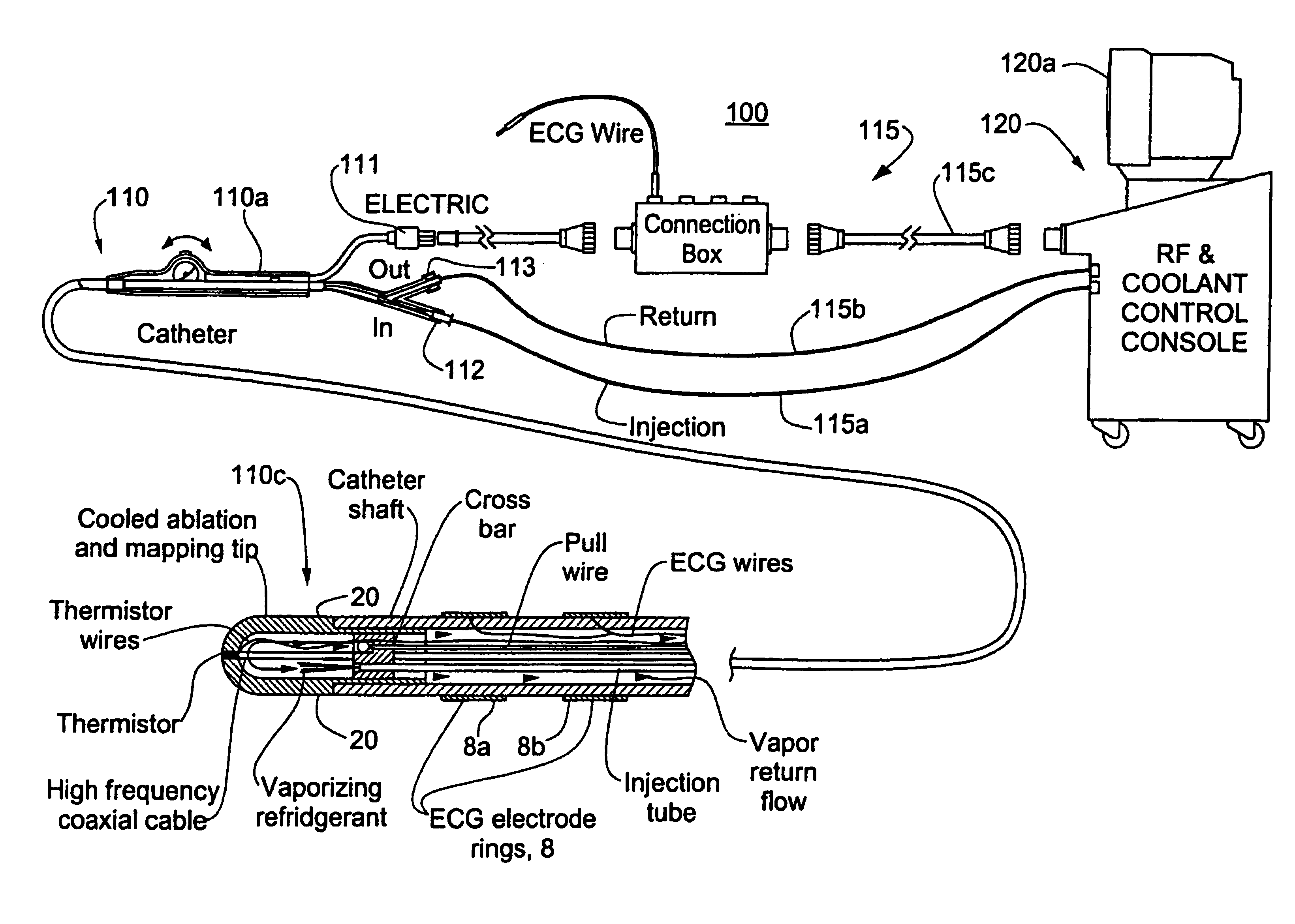
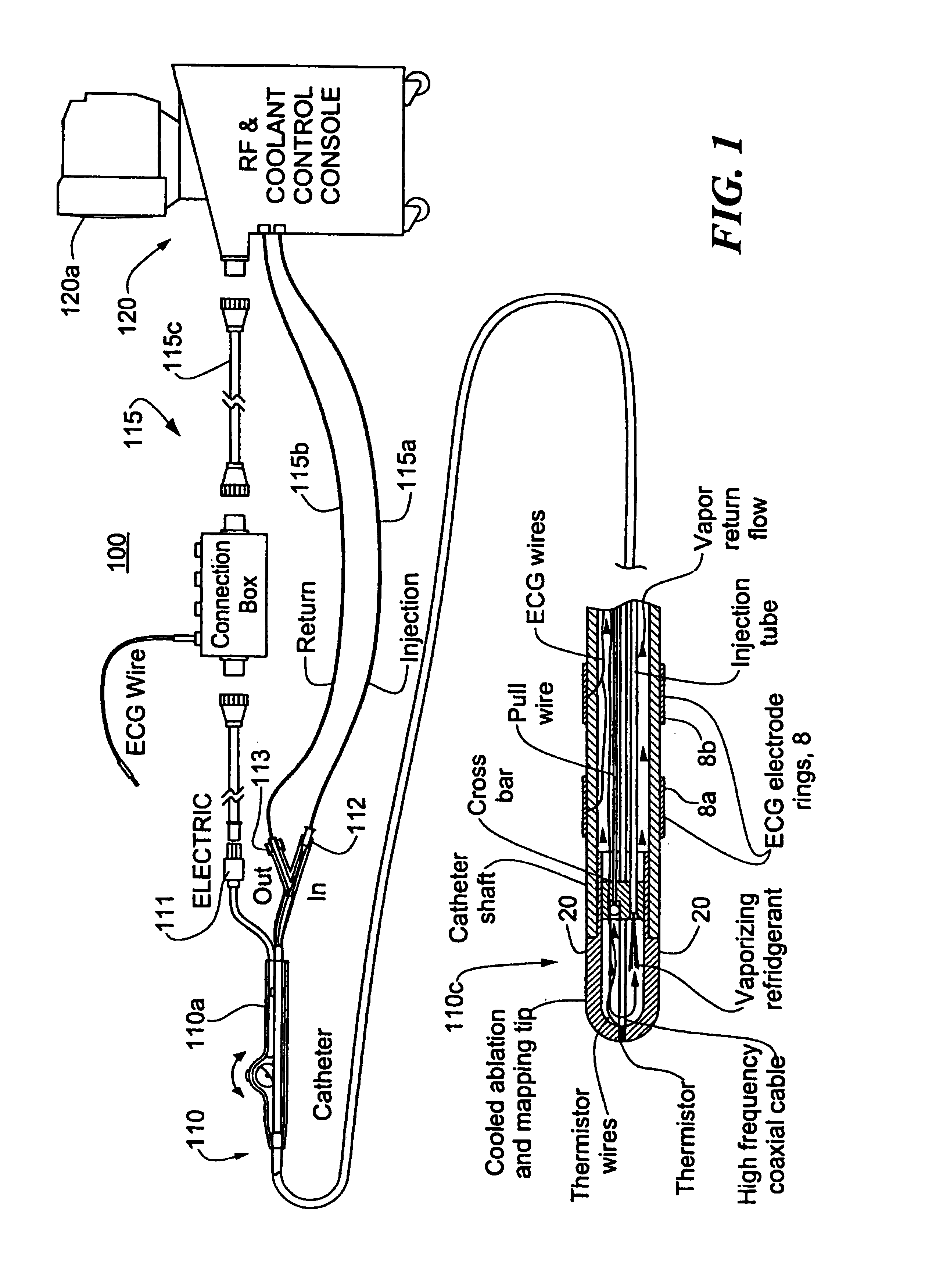
[0018]FIG. 1 shows a first embodiment of a cryogenic treatment system 100 of the present invention and illustrative elements thereof. System 100 includes a treatment catheter 110 having a handle 110a, and elongated cryogen transporting body 110b and a catheter tip 110c. The catheter 110 is connected by various conduits or cables to a console 120 which may, for example, have a display monitor 120a and other data entry or display accessories such as a keyboard, a printer and the like. The console 120 is connected to the catheter by various lines 115 which may include a coolant injection line 115a, a coolant return line 115b, and electrical cabling 115c which includes an RF drive line and may further carry console control outputs such as valve or switching signals, and outputs of various cardiac sensing, thermal sensing, mapping or other elements for catheter treatment or monitoring. As shown, the handle 110a is equipped with input ports for electrical connectors 111, a coolant injecti...


PUM


Abstract

A catheter includes a cryoablation tip with an electrically-driven ablation assembly for heating tissue. The cryoablation tip may be implemented with a cooling chamber through which a controllably injected coolant circulates to lower the tip temperature, and having an RF electrode at its distal end. The RF electrode may be operated to warm cryogenically-cooled tissue, or the coolant may be controlled to conductively cool the tissue in coordination with an RF treatment regimen, allowing greater versatility of operation and enhancing the lesion size, speed or placement of multi-lesion treatment or single lesion re-treatment cycles. In one embodiment a microwave energy source operates at a frequency to extend beyond the thermal conduction depth, or to penetrate the cryogenic ice ball and be absorbed in tissue beyond an ice boundary, thus extending the depth and / or width of a single treatment locus. In another embodiment, the cooling and the application of RF energy are both controlled to position the ablation region away from the surface contacted by the electrode, for example to leave surface tissue unharmed while ablating at depth or to provide an ablation band of greater uniformity with increasing depth. The driver or RF energy source may supply microwave energy at a frequency effective to penetrate the ice ball which develops on a cryocatheter, and different frequencies may be selected for preferential absorption in a layer of defined thickness at depth in the nearby tissue. The catheter may operate between 70 and minus 70 degrees Celsius for different tissue applications, such as angioplasty, cardiac ablation and tissue remodeling, and may preset the temperature of the tip or adjacent tissue, and otherwise overlay or delay the two different profiles to tailor the shape or position where ablation occurs or to speed up a treatment cycle.

Description

CROSS-REFERENCE TO RELATED APPLICATIONS[0001]Not Applicable.STATEMENT REGARDING FEDERALLY SPONSORED RESEARCH[0002]Not Applicable.BACKGROUND OF THE INVENTION[0003]The present application relates to cryocatheters and wands, i.e. to catheters and wands which are used to locally ablate tissue by extreme cooling contact. Such implements, henceforth generically referred to herein as “cryocatheters” or simply “catheters” may, for example, have an elongated body through which a cooling fluid circulates to a tip portion which is adapted to contact and freeze tissue. The invention also relates to cold-mapping catheters. In general, such catheters may be used to lower the temperature of tissue, such as cardiac wall tissue, to an extent such that signal generation or conduction ceases and allows one to map or confirm that the catheter is positioned at a particular lesion or arrhythmia conduction site. Cryocatheters, however, operate at lower temperatures, and are configured for ablation treatme...

Claims


Application Information

Patent Timeline
Patent Type & Authority Patents(United States)
IPC IPC(8): A61B18/18A61B17/00A61B18/02A61B18/14
CPCA61B18/02A61B18/1492A61B2018/0268A61B2017/00243A61B2018/0212A61B18/18
Inventor ARLESS, STEVEN G.MILDER, FREDERIC L.ABBOUD, MARWANWITTENBERGER, DANCARROLL, SEAN
Owner MEDTRONIC CRYOCATH LP
Why Eureka
Try Eureka