Docking system for MP3 players and other portable electronic devices

a portable electronic device and docking system technology, applied in the direction of electrical apparatus casings/cabinets/drawers, instruments, cabinets, etc., can solve the problems of not being able to easily fix, the connectors used on one device do not match the connectors conventionally, and the docks tend to suffer

Inactive Publication Date: 2010-08-17
MOHONEY VICTOR
View PDF50 Cites 140 Cited by
  • Summary
  • Abstract
  • Description
  • Claims
  • Application Information

AI Technical Summary

Benefits of technology

[0008]The device sleeve 200 is configured to extend about a portion of the exterior of the portable electronic device 10 to removably engage the portable electronic device 10 within the device sleeve 200. Windows / ports formed in the device sleeve 200 leave the device connection port 16 exposed, as better seen in FIG. 3. The device sleeve 200 includes a sleeve body 202 having a top sleeve side 204 and an opposing bottom sleeve side 206; a front sleeve side 208 and an opposing rear sleeve side 210 which extend between the top and bottom sleeve sides 204 and 206; and opposing lateral sleeve sidewalls 212 extending between the top and bottom sleeve sides 204 and 206, and also between the front and rear sleeve sides 208 and 210. The sleeve sidewalls 212 extend outwardly from the sleeve body 202 to define a device insertion space 214 (see FIGS. 1-2) between the sleeve sidewalls 212, and adjacent the sleeve body 202, into which the portable electronic device 10 may be inserted. The sleeve sidewalls 212 include concave inner sidewall faces 216 which face inwardly toward each other across the device insertion space 214, wherein the portable electronic device 10 may rest within the device insertion space 214 with edges of the portable electronic device 10 received within the concave inner sidewall faces 216. The sleeve sidewalls 212 are preferably spaced at least substantially uniformly away from each other save for at the top and bottom sleeve sides 204 and 206, where the sleeve sidewalls 212 may extend inwardly toward each other. As a result, the device insertion space 214 is narrower at the top and bottom sleeve sides 204 and 206 and broader therebetween, with the inwardly-extending sidewalls 212 at the top and bottom sleeve sides 204 and 206 and the concavity of the inner sidewall faces 216 assisting in firmly retaining the portable electronic device 10 within the device sleeve 200. At the same time, as seen in FIG. 5 (which presents a cross-sectional view of FIG. 4), the sleeve body 202 is preferably formed thinner at a location 218 spaced at least substantially halfway between the sleeve sidewalls 212, and extending between the top and bottom sleeve sides 204 and 206, thereby allowing the sleeve sidewalls 212 to flex apart so that the portable electronic device 10 may be snapped into and out of the device sleeve 200 (provided it is made of appropriately flexible plastic, metal, or other materials).
[0014]The system can be provided with additional components / accessories to further enhance its versatility. One such accessory is illustrated in FIG. 1 in the form of a sleeve cover 250, which removably engages the device sleeve 200 to fit over the exposed front face 12 of the portable electronic device 10, thereby further protecting the portable electronic device 10 (see FIG. 7). The sleeve cover 250 has a cover body 252 with a clip 254 to allow a user to clip the portable electronic device 10, with device sleeve 200 and sleeve cover 250, to a belt, pocket, or the like. The sleeve cover 250 has opposing top and bottom cover sides 256 and 258, and opposing lateral cover sidewalls 260 which extend outwardly from opposite sides of the cover body 252 between the top and bottom cover sides 256 and 258. The cover sidewalls 260 include inner sidewall faces 262 facing inwardly toward each other across a sleeve insertion space 264 defined between the inner sidewall faces 262 and adjacent the cover body 252, with the inner sidewall faces 262 being concave. The sleeve cover 250 may then receive the device sleeve 200 within the sleeve insertion space 264 with the sleeve ridges 222 being received within the concave inner sidewall faces 262 of the cover sidewalls 260, allowing the sleeve cover 250 to be “snapped” onto or off of the device sleeve 200. So that the sleeve cover 250 may have a thinner profile, the sleeve ridges 222 on the device sleeve 200 are preferably spaced closer to the front sleeve side 208 than the rear sleeve side 210. The sleeve cover 250 usefully addresses a problem common with prior device sleeves in that these either do not bear clips, and provide no easy means for attaching a clip, or otherwise permanently bear a clip and are therefore bulky and inconvenient for use when the user has no need for the clip.

Problems solved by technology

However, a commonly encountered problem is that the connectors conventionally used on one device do not match the connectors conventionally used on the other device; for example, a computer might have one or more USB (Universal Serial Bus) connectors, or a vehicle's stereo system might utilize an RCA connector, whereas an IPOD portable media player or IPHONE mobile telephone (from Apple Inc., Cupertino, Calif., USA) might use a proprietary 30-pin connector.
Docks tend to suffer from the drawback that the dock sockets are typically designed to accommodate only a single specific make / model of portable electronic device, i.e., only a particular portable electronic device will properly fit within a given dock socket.
For example, a user may need to obtain one dock to allow interfacing between his portable media player and the stereo system of his vehicle, and another dock to allow interfacing between another portable media player and the stereo system of the vehicle, even where the terminal connectors of the different portable media players are the same: the different configurations of the portable media players do not allow them to fit into a common dock socket.
The problem is not easily remedied by simply having a variety of different docks on hand, since swapping one dock for the other may be difficult and inconvenient depending on the type and location of the dock's connection to the vehicle.
The foregoing problems might be referred to as the “interface problem” (the problem of providing an interface connector compatible with a particular portable electronic device) and the “socket problem” (the problem of providing a socket compatible with a particular portable electronic device, wherein the device can be properly fit).
Docks often suffer from the interface problem as well as the socket problem, which has further limited their popularity.

Method used


Image

  • Docking system for MP3 players and other portable electronic devices
  • Docking system for MP3 players and other portable electronic devices
  • Docking system for MP3 players and other portable electronic devices

Examples


Embodiment Construction

[0039]Throughout this document, unless specified otherwise, the following terms should be understood to have the following meanings.

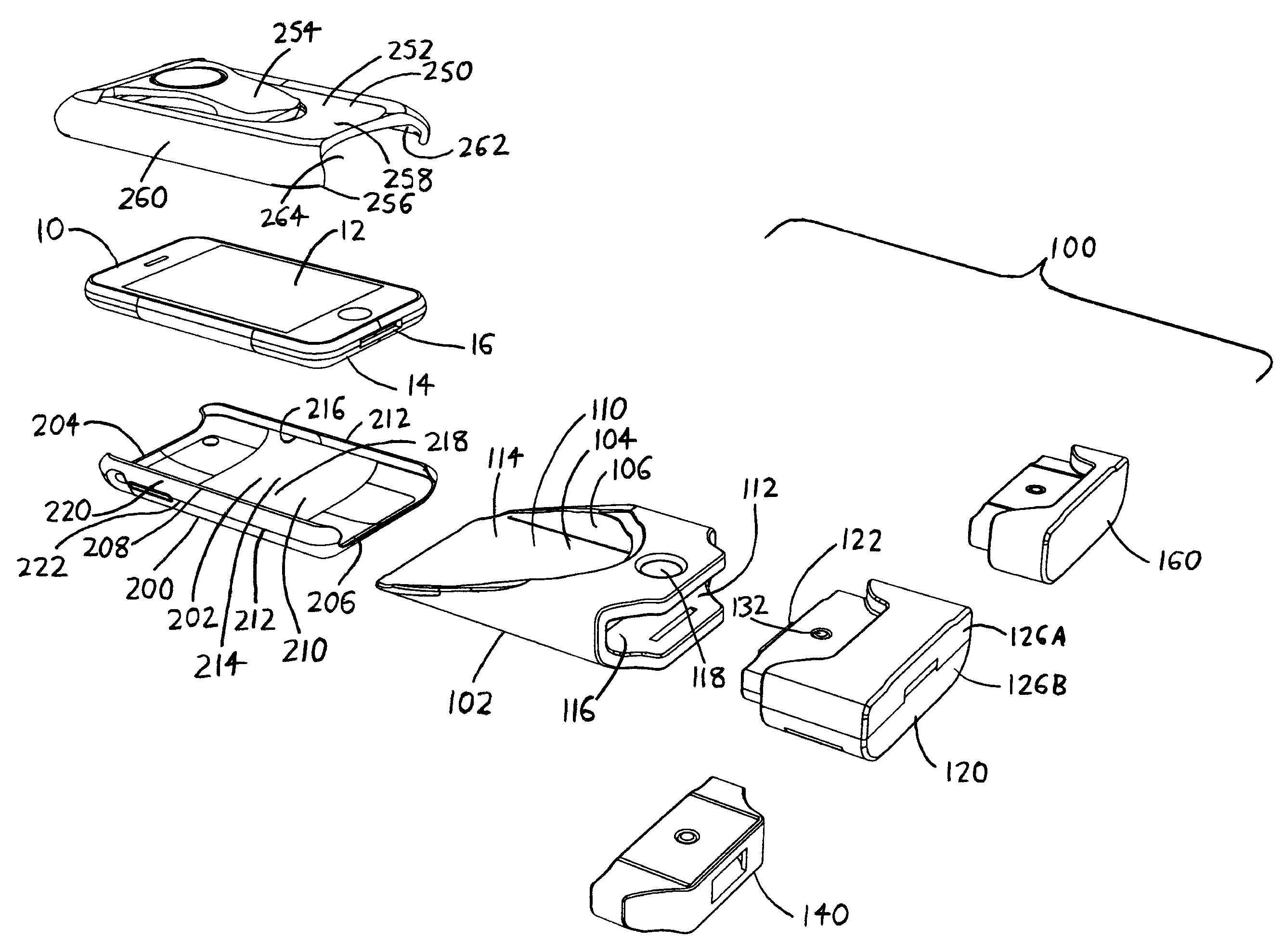
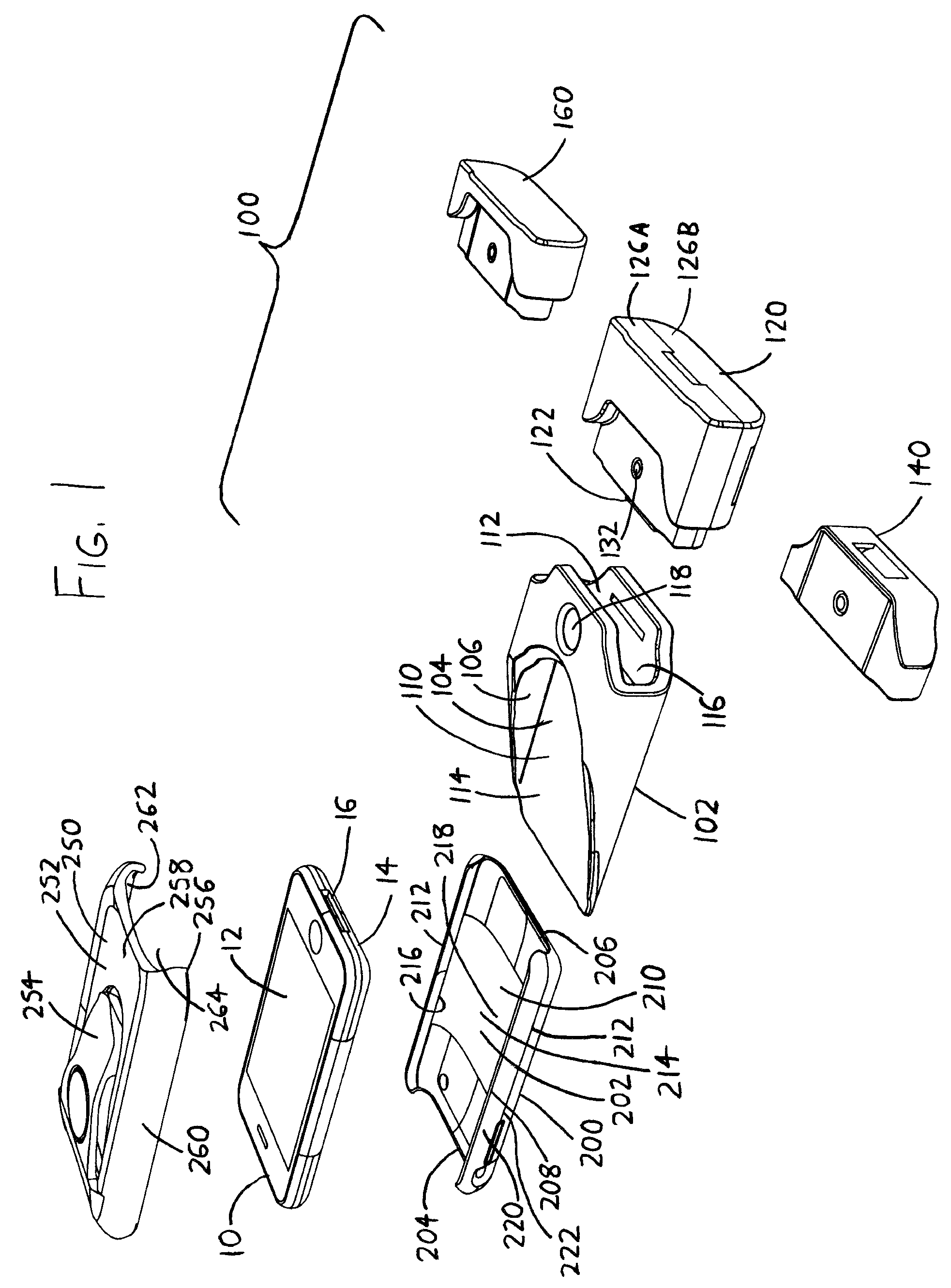
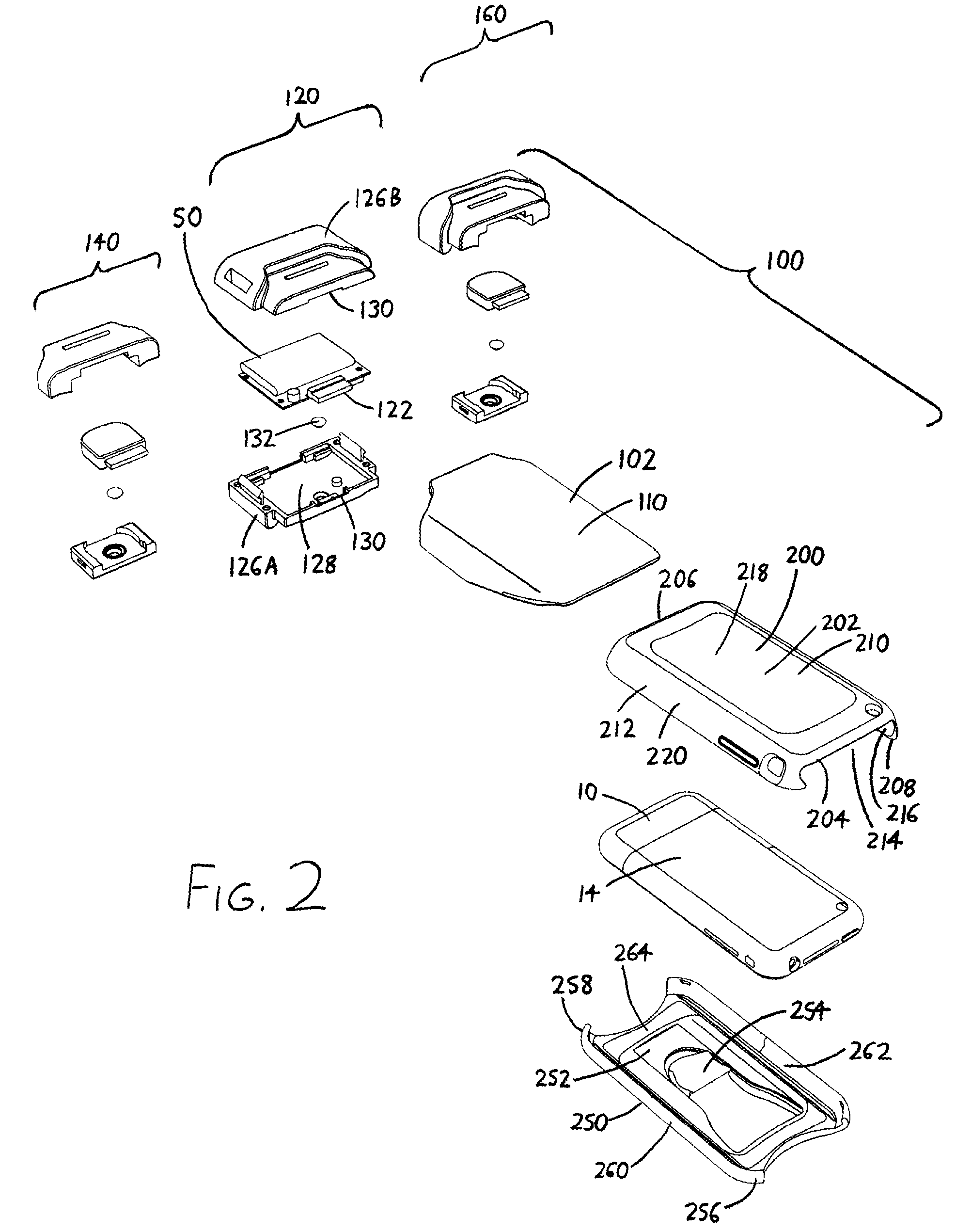
[0040]The term “deviceconnection port,” when referring to a connection port of a portable electronic device, refers to a port for the input and / or output of signals (such as data) and / or power. As examples, a device connection port might be a female socket (or male plug) for transmission of DC power into and / or out of the electronic device; a female socket (or male plug) meeting the RS-232 standard for transmission of data into and / or out of the electronic device; or a female socket (or male plug) meeting the USB standard for transmission of data into and / or power into and / or out of the electronic device. In the context of the preferred versions of the invention illustrated in the accompanying drawings, the device connection port is generally depicted as a 30-pin connector, which is (at the time of this document's preparation) conventionally used in IPO...


PUM


Abstract

Sleeves for different portable electronic devices (portable media players, wireless telephones, handheld computers, etc.) adapt the outer contours of the devices such that all can fit within the pocket of a standard device dock. Each sleeve situates its portable electronic device within the pocket of the dock such that at least one of its power / communications ports is situated at a standard location. The device dock then also accommodates a connector which fits within the dock pocket, and which has power / communications ports situated at the standard location, such that when the sleeved device is inserted into the pocket, its power / communications ports interface with the power / communications ports of the connector. The connector can incorporate data storage devices, power supplies, interface cables extending to other devices (such as personal computers, stereo systems, etc.) such that it lends the functionality of these devices to the sleeved device situated within the pocket.

Description

CROSS-REFERENCE TO RELATED APPLICATIONS[0001]This application claims priority under 35 USC §119(e) to U.S. Provisional Patent Application 61 / 098,483 filed 19 Sep. 2008, the entirety of which is incorporated by reference herein.FIELD OF THE INVENTION[0002]This document concerns an invention relating generally to interface and docking systems for portable electronic devices such as wireless telephones, handheld computers, and handheld portable media players (e.g., MP3 players), and more specifically to docking systems which can accommodate a variety of different portable electronic devices and which can be readily reconfigured to provide different functionality for a portable electronic device.BACKGROUND OF THE INVENTION[0003]Portable electronic devices such as wireless telephones, handheld computers, and handheld portable media players (e.g., MP3 players) are in common use, and are often designed to interface with another device such as a computer, the stereo system of a vehicle, an ...

Claims


Application Information

Patent Timeline
Patent Type & Authority Patents(United States)
IPC IPC(8): G06F1/16
CPCG06F1/1632
Inventor MOHONEY, VICTOR
Owner MOHONEY VICTOR
Why Eureka
Try Eureka