
Enhanced hollow foam tire structure

a technology of hollow foam tires and foam tires, which is applied in the field of hollow foam tires, can solve the problems of pneumatic tires that have the risk of puncture and flattening, the carrying capacity is still insufficient, and the carrying capacity is still very limited, so as to enhance the loading capacity, strengthen the structure of the hollow foam tires, and improve the elastic and loading capacity of the tires.

Inactive Publication Date: 2006-02-09
HAN WEN YAO
View PDF21 Cites 19 Cited by
  • Summary
  • Abstract
  • Description
  • Claims
  • Application Information

AI Technical Summary

Benefits of technology

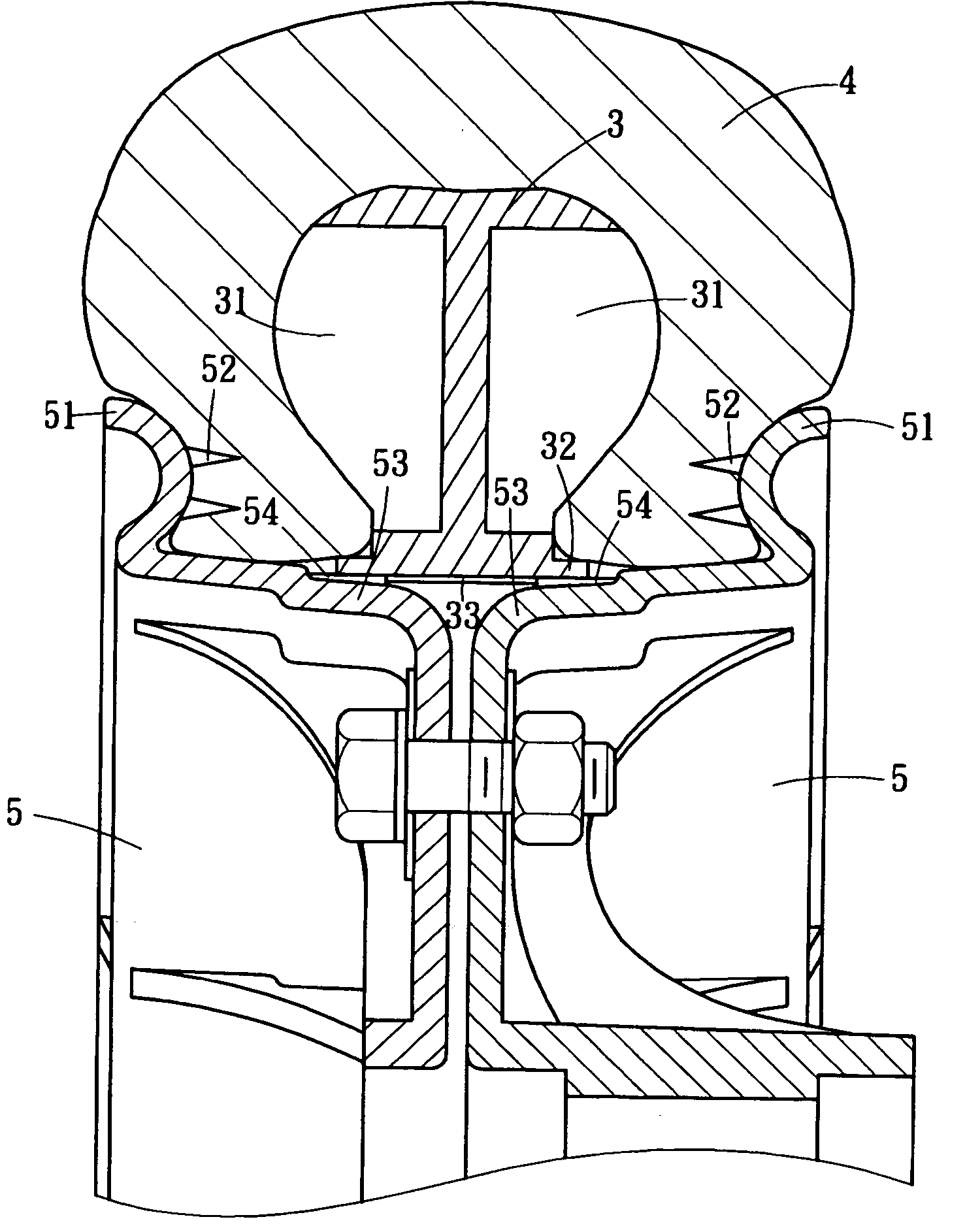
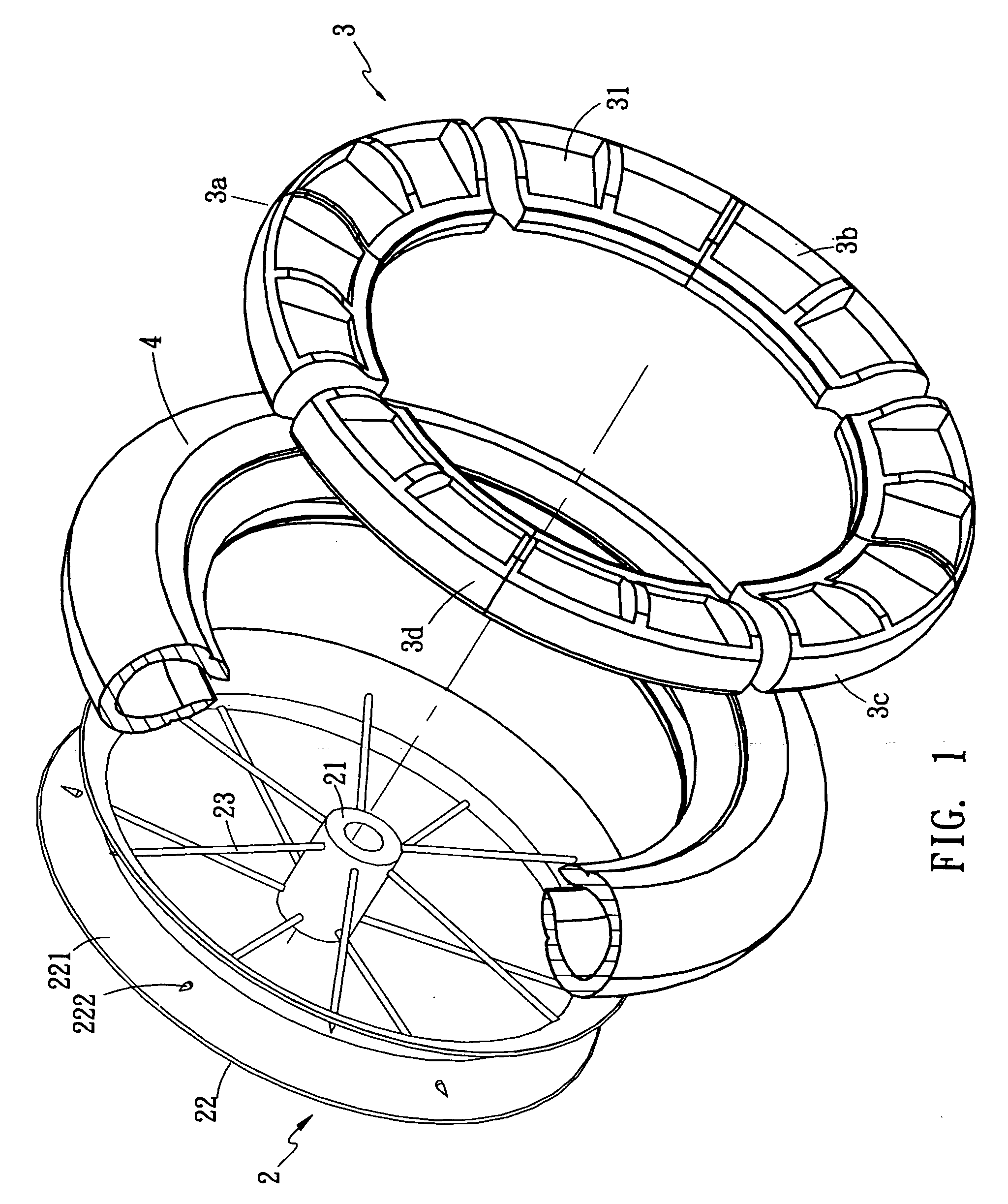
[0004] It is therefore a primary objective of the present invention to overcome the condition of maintaining a good elastic and loading capability of a tire without air inflation. The tire according to the present invention is made of EVA materials and substantially hollow, and the tire comprises a wheel core in an annular shape formed by a plurality of separated sections and a rim clamped on both sides of the tire. In addition to strengthening the structure of the EVA tire, the present invention also enhances its loading capacity and also maintains an excellent elasticity.
[0005] Further, a protruded section disposed on the two corresponding inboard sides of the foregoing rim and the sides of the wheel core are substantially hollow, such that the tire can engage the rim and wheel cores better as to further prevent the EVA foam tire from skidding.

Problems solved by technology

Although the tire of this kind is solid, the carrying capacity is still insufficient due to its manufacturing material.
Although a pneumatic tire with this structure has better elasticity and cushioning effect, its carrying capacity is still very limited.
Furthermore, the pneumatic tire also has the risk of being punctured and flatted.

Method used


Image

  • Enhanced hollow foam tire structure
  • Enhanced hollow foam tire structure
  • Enhanced hollow foam tire structure

Examples


Embodiment Construction

[0012] Please refer to FIGS. 1 and 2 for the present invention. In the figures, a wheel rim 2 of the foam tire comprises a plurality of spokes 23 connected between a hub 21 and a rim 22, a plurality of pointed splinters 222 evenly disposed on the concave surface of the rim 22 and a wheel core 3 formed by a plurality of separated sections 3a, 3b, 3c, 3d. A hollow section 31 is alternatively disposed on both sides of each separated section 3a, 3b, 3c, 3d, and each separated section 3a, 3b, 3c, 3d is pre-installed into a hollow foam tire 4. The tire 4 together with the wheel core 3 are sheathed onto the rim 22 of the wheel rim 2 as to pierce each pointed splinter 222 into the tire 4 and fix the tire 4 into place, and thus prevent skids between the wheel rim 2 and the tire 4. Furthermore, the hollow tire 4 wraps the wheel core 3, and thus the foam tire can carry heavier loads.

[0013] Please refer to FIGS. 3 and 4 for another preferred embodiment of the present invention. The wheel rim 5...


PUM


Abstract

This invention discloses a hollow EVA foam tire structure capable of carrying heavy loads, particularly a hollow EVA form tire having an accommodating space between the inboard sides of the tire. The tire is comprised of a plurality of sections substantially arranged into an annular shape, and a wheel core being hollow on both sides, such that a plurality of protruded block sections is disposed on the internal side of the flange section extended from the accommodating space and both sides of the tire are covered by a rim having two corresponding external flange surfaces at the external sides, and a pointed splinter is disposed on the internal side of the external flange surface and a protruded block section is protruded from the surrounding surface of the flange end at the internal side of the rim, so that the protruded block sections of the wheel core are alternatively and mutually engaged. Therefore, when the two corresponding rims are securely coupled, the pointed splinters of the rim can be pierced and fixed into the tire, and the internal side of the tire is embedded into the hollow section of the wheel core by the compressed force. Therefore, the tire, the wheel core and the two side rims can be coupled more securely so as to enhance the carrying capacity of the tire by the wheel core.

Description

FIELD OF THE INVENTION [0001] The present invention relates to hollow ethylene-vinyl acetate (EVA) foam tires having an enhanced wheel core and a rim for being clamped on both sides, such that the three parts can be connected more securely as to enhance the loading capacity of the tire. BACKGROUND OF THE INVENTION [0002] In general, a solid tire made of ethylene-vinyl acetate (EVA) foam material is commonly used for vehicles carrying less load and having no absorber but demanding a good shockproof function, because such tire has the features of low cost, easy manufacturing and outstanding elasticity. Although the tire of this kind is solid, the carrying capacity is still insufficient due to its manufacturing material. However, the U.S. Pat. No. 4,216,810 disclosed a tire structure which comprises a plurality of annularly disposed circular protector elements keeping an appropriate distance from the inner wall of the wire and a flange being accommodated precisely between both inboard ...

Claims


Application Information

Patent Timeline
Patent Type & Authority Applications(United States)
IPC IPC(8): B60C7/24
CPCB60B1/02B60B3/08B60B21/104B60B21/12B60B23/10Y10T152/10432B60B25/22B60C7/08B60C7/105B60C7/24Y10T152/10396B60B25/002
Inventor HAN, WEN-YAO
Owner HAN WEN YAO
Learn More