Adaptive-scanning optical microscope

an optical microscope and adaptive scanning technology, applied in the field of optical microscopy, can solve the problems of significant design and implementation challenges in system configuration, and achieve the effect of improving performan

Active Publication Date: 2007-11-01
RENESSELAER POLYTECHNIC INST
View PDF3 Cites 62 Cited by
  • Summary
  • Abstract
  • Description
  • Claims
  • Application Information

AI Technical Summary

Benefits of technology

[0022] It is an object of the present invention to provide an adaptive scanning optical

Problems solved by technology

However, such a system configuration also poses significant design and implementation chal

Method used


Image

  • Adaptive-scanning optical microscope
  • Adaptive-scanning optical microscope
  • Adaptive-scanning optical microscope

Examples


Embodiment Construction

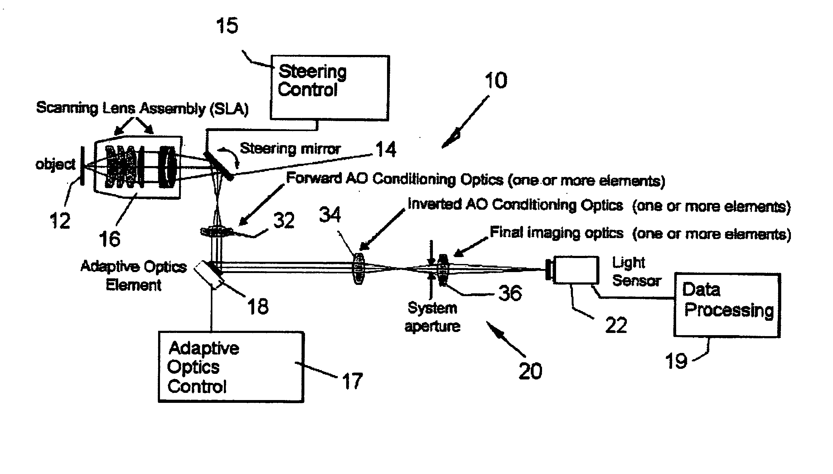
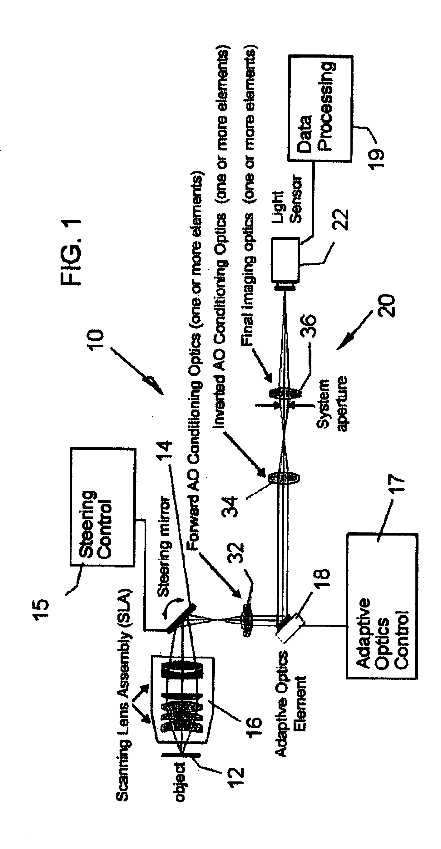
[0045] Referring now to the drawings, in which like reference numerals are used to refer to the same or similar elements, FIG. 1 shows the adaptive scanning optical microscope or ASOM 10 which operates by taking a sequence of small spatially displaced images in succession from an object 12, and then assembling a large composite image (mosaic) or several disjoint or possibly overlapping images of the scene.

[0046] While the general concept of expanding the field of view while preserving resolving power through mosaic construction is known and has been applied to biological imaging (see J. Zemek, C. Monks, and B. Freiberg, “Discovery through automation,” Biophotonics International 10, 54-57 (2003)) as well as to industrial imaging (see C. Guestrin, F. Cozman, and S. Godoy, “Industrial applications of image mosaicing and stabilization,” in Proceedings of IEEE International Conference on Knowledge-Based Intelligent Electronic Systems—Institute of Electrical and Electronics Engineers, Ne...


PUM


Abstract

An adaptive scanning optical microscope has a scanner lens assembly for acquiring images from different parts of an object plane and for forming a preferably curved image field having at least some aberration which varies as a function of the part of the object plane from which the image is acquired. A steering mirror selects the field of view and steers light from the object and along a light path from the object plane to a final image plane. An adaptive optics element receives the steered light from the object and compensates for the field position dependent optical aberrations and additional optics are along at least part of the light path for conditioning and focusing the light as it moves from the steering mirror, past the adaptive optics element and to the final image plane.

Description

CROSS-REFERENCE TO RELATED APPLICATION [0001] This application claims priority on PCT / US2005 / 047287, filed Dec. 29, 2005, which claims priority on U.S. Provisional Patent Application No. 60 / 647,572, filed Jan. 27, 2005, which application is incorporated here by reference.FIELD AND BACKGROUND OF THE INVENTION [0002] The present invention relates generally to the field of optical microscopy and, in particular, to a new and useful adaptive scanning optical microscope which addresses and improves upon, the usual trade-off between resolution and field of view that is common for known optical microscopes. [0003] The inventors have disclosed an earlier approach to solving this trade-off problem in U.S. patent application Ser. No. 10 / 525,422 filed Feb. 25, 2005. This application claims priority on U.S. Provisional Patent Application No. 60 / 411,038 and International Application No. PCT / US2003 / 029332, published as WO 2004 / 025331, all of which are also incorporated here by reference. [0004] Fo...

Claims


Application Information

Patent Timeline
IPC IPC(8): G02B21/00
CPCG02B21/0048G02B21/002
Inventor POTSAID, BENJAMINBELLOUARD, YVESWEN, JOHN
Owner RENESSELAER POLYTECHNIC INST
Why Eureka
Try Eureka