[0005]Mp images can be processed by various techniques that draw attention to selected portions or features of these images, such as CAD (
computer aided detection) techniques that analyze the images to identify likely abnormalities and place markers on a breast image or representation that identify the location and in some cases the type or other information about the likely abnormalities. Some of the parent applications identified above describe applying CAD analysis to Tr and / or Tp images as well, or as an alternative or an adjunct to applying CAD to Mp images, and also describe how to improve the presentations of Tp and / or Tr images (collectively referred to here as T images), Mp images, and CAD and / or other information about the images to make the review by
health professionals more effective and efficient.
[0009]Microcalcifications seen in breast images are considered important clues in screening and / or diagnosis, and prior proposals have been directed to identifying particular specific patterns of microcalcifications or all microcalcifications, or at least those having specified characteristics such as size or density. This patent specification takes a different approach by not only necessarily seeking to identify and classify patterns of
microcalcification distributions in images, or to identify or enhance all microcalcifications detectable in the image, but rather to facilitate the
visualization of up to a certain number of selected suspected calcifications that meet various special thresholds in a given image or volume of tissue in ways that are particularly useful to the health professional. Calcifications often have a typical x-
ray absorption characteristic, but not all objects with these absorption characteristics are calcifications or are of
clinical value. Calcifications of clinical interest generally fall in a certain range of sizes and shapes and patterns. The largest calcifications are often benign. Linear ones also are often benign. Identifying all of the very smallest
calcification-like objects runs the risk that some of them might represent
noise and not true calcifications or reasonably suspected calcifications. One object of the approach disclosed in this patent specification is to reduce the number of identified possible or suspected calcifications which are of lower
clinical value.
[0010]As one non-limiting example, the approach disclosed in this patent specification involves examining through
computer processing the individual Tr images in a 3D set of such images to identify an initial set of possible calcifications that meets a threshold limiting the number of identified calcifications in a given Tr image, or in the entire 3D set or a selected subset of the entire 3D set, to a specified number of calcifications and / or number of pixels that are determined to correspond to calcifications. Preferably, the Tr images are presented for this examination after filtering with a
mask that enhances
high spatial frequency image features. The process removes from the initial set, pixels initially determined to relate to calcifications that are too large in area or too long in linear extent, and may additionally impose other constraints such as excluding initially determined calcifications that are not present in two adjacent Tr images, applying
ligament removal and edge
removal techniques, requiring at least a certain number of calcifications to be in a specified volume of the 3D set, and excluding calcifications that are in the initial and trailing Tr images in a stack of Tr images and thus are likely to be at the
skin level and unlikely to have
clinical significance. The removal processes are designed to remove calcifications that are likely to be devoid of clinical interest and to remove
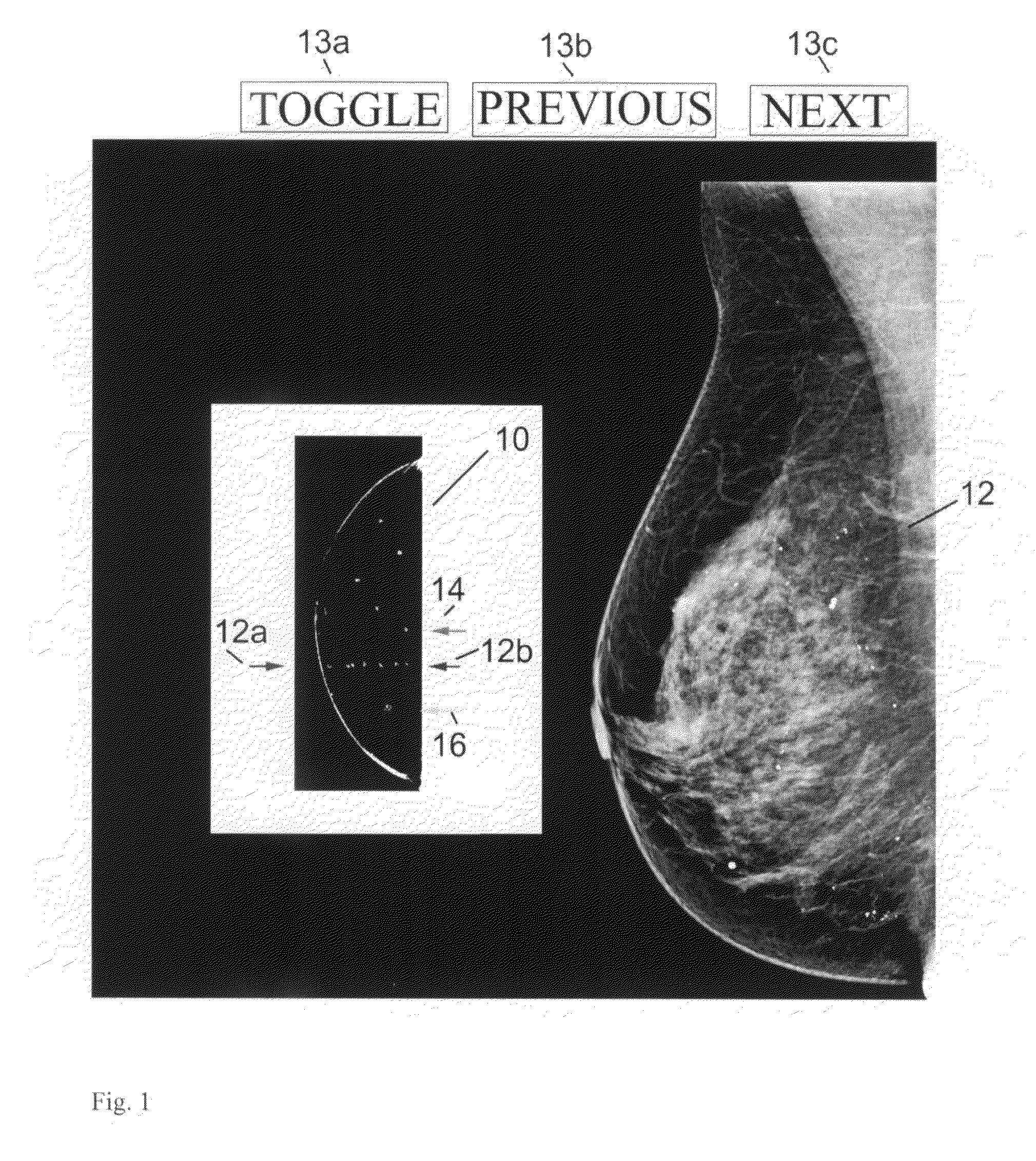
noise and other non-calcification objects. In displaying the results, one example is to show a scout view that generally conforms in shape to a projection of the breast and shows a distribution of identified calcifications as well as a current level that both (1) includes calcifications and (2) corresponds to a Tr image that is orthogonal to the scout image and is seen at a main
image display. Alternatively, this information can be displayed using a ruler or other
schematic display that does not conform in shape to a projection of the breast but still allows display of the current level and / or the locations of likely calcifications. Thus, the current level in the 2D scout or
schematic view points to one or more corresponding Tr images. The scout or
schematic view also shows a pointer to a next level that contains identified calcifications so that a user can conveniently click on that level and thus call on the main display the next Tr image of interest. The scout or schematic view may also indicate how many calcification clusters are in a given Tr image. In addition, the user can toggle the main display between showing a Tr image with or without highlighted calcifications therein. A health professional thus can quickly and effectively review Tr images that are likely to be of interest. The health professional can additionally select for the main display additional Tr images, Tr images that are for thick or thin slices and / or reconstructed in another orientation, Tp images and / or Mp images.
[0011]An alternative or additional process is to initially search Tp and / or Mp images rather than the 3D set of Tr images to identify likely calcifications of interest. This can be done using CAD as disclosed in the
patent literature incorporated by reference in this patent specification, or by adapting the principles discussed above for identifying calcifications in Tr images and 3D volumes, or in some other manner. After likely calcifications of
clinical significance are identified in the 2D Tp and / or Mp images, the 2D images can be displayed one at a time or several at a time, or only those 2D images that have identified calcifications can be displayed. When a user points to a likely calcification in a displayed 2D image, e.g., by a mouse click on the calcification in a 2D image,
computer processing can search through the Tr images of the breast to identify and display the Tr image or Tr images that contain that calcification. This search through the Tr images can use knowledge about the location of the likely calcification in the 2D image, on parameters of the calcification such as its size, shape, pixel values and distribution of those values in the 2D image, and possibly other parameters. In case of an
ambiguity, i.e., the calcification pointed to in the 2D image appears in two or more Tr images, all possibly relevant Tr images can be displayed to the user, singly or in a set or subsets or in cine mode, and the user may select for further use the ones that appear relevant or dismiss any that are not. This alternative can reduce
processing time because the search for likely calcifications in the 2D images can be faster, and the subsequent search for the Tr slice(s) that contain a calcification to which the user pointed in a 2D image also can be faster. One reason for greater computational efficiency is that the 3D
data set (the Tr images) need to be processed only after a likely calcification has been selected, so only a relatively small volume of the 3D set would need to be searched. Another
advantage of this alternative may be if the search process is more sensitive and / or more accurate for 2D images. If so, then it is more likely to decrease the overall rate of false negatives and / or false positives in identifying likely calcifications, and thus improve the presentation of images to the health professional and make the overall process of assessing the images for screening, diagnosis, or other purposes, more effective and / or more efficient.

