Sinus illumination lightwire device

a lightwire device and sinus cavity technology, applied in the field of sinus cavity illumination lightwire devices, can solve the problems of damage to the epithelium that lines the sinuses, blocked passageways which drain through the sinuses, and mucosal congestion within the paranasal sinuses, and achieve the effect of facilitating visualization of target anatomy

Active Publication Date: 2008-09-18
ACCLARENT INC
View PDF57 Cites 252 Cited by
  • Summary
  • Abstract
  • Description
  • Claims
  • Application Information

AI Technical Summary

Benefits of technology

[0011]Briefly and in general terms, the present disclosure is directed towards an apparatus and method for facilitating visualization of target anatomy. In one approach, the apparatus is embodied in an illuminating device configured to be positioned at or adjacent anatomy within a patient's body. The illuminating device can be employed to provide transillumination.
[0014]Further, approaches to compensating for changing lengths of an illumination fiber are contemplated as are approaches to facilitating the operation of the illuminating device. In that regard, structure can be incorporated into the illuminating device to accommodate changes in length or steps can be taken to treat the illumination fiber to control length changes. Also, drugs can be injected at an interventional site to aid the illumination process.
[0033]In at least one embodiment, visualization of the advancement of the sinus guide is through use of the scope, up to a limit of adequate illumination by the scope. After that, the light emitted by the distal end portion of the illuminating device, having been advanced distally of a distal end of the sinus guide, extends the limit of adequate illumination of the scope, thereby extending a length of the adequate illumination of the scope.
[0034]In at least one embodiment, the sinus guide can be further distally advanced under visualization by the scope as facilitated by the extended length of the adequate illumination.
[0040]In at least one embodiment, further advancement of the sinus guide toward an ostium of a sinus is visualized via the scope as facilitated by the extended length of adequate illumination provided by the illumination device.
[0042]In at least one embodiment, the distal end portion of the illuminating device is advanced further distally of a distal end of the sinus guide and distal of the limit of illumination of the scope to emit illumination, thereby extending a length of a space that is visualizable by the scope.

Problems solved by technology

If the mucosal tissue of one of these passageways becomes inflamed for any reason, the cavities which drain through that passageway can become blocked.
This interference with drainage of mucus (e.g., occlusion of a sinus ostium) can result in mucosal congestion within the paranasal sinuses.
Chronic mucosal congestion of the sinuses can cause damage to the epithelium that lines the sinus with subsequent decreased oxygen tension and microbial growth (e.g., a sinus infection).
A large number of patients do not respond to drug therapy.
For example, FESS can cause significant post-operative pain.
Also, some FESS procedures are associated with significant postoperative bleeding and, as a result, nasal packing is frequently placed in the patient's nose for some period of time following the surgery.
Such nasal packing can be uncomfortable and can interfere with normal breathing, eating, drinking etc.
Also, some patients remain symptomatic even after multiple FESS surgeries.
Additionally, some FESS procedures are associated with risks of iatrogenic orbital, intracranial and sinonasal injury.
Thus, patients with less severe disease may not be considered candidates for FESS.
One of the reasons why FESS procedures can be bloody and painful relates to the fact that instruments having straight, rigid shafts are used.
In some cases, such dilatation of the ostium may fracture, move or remodel bony structures that surround or are adjacent to the ostium.
Reaching and accessing target anatomy can be a challenge in general and more so in particular patients as anatomy can both be variable and unpredictable.

Method used


Image

  • Sinus illumination lightwire device
  • Sinus illumination lightwire device
  • Sinus illumination lightwire device

Examples


Embodiment Construction

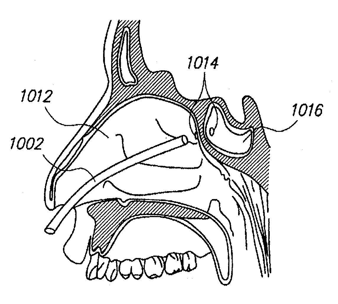
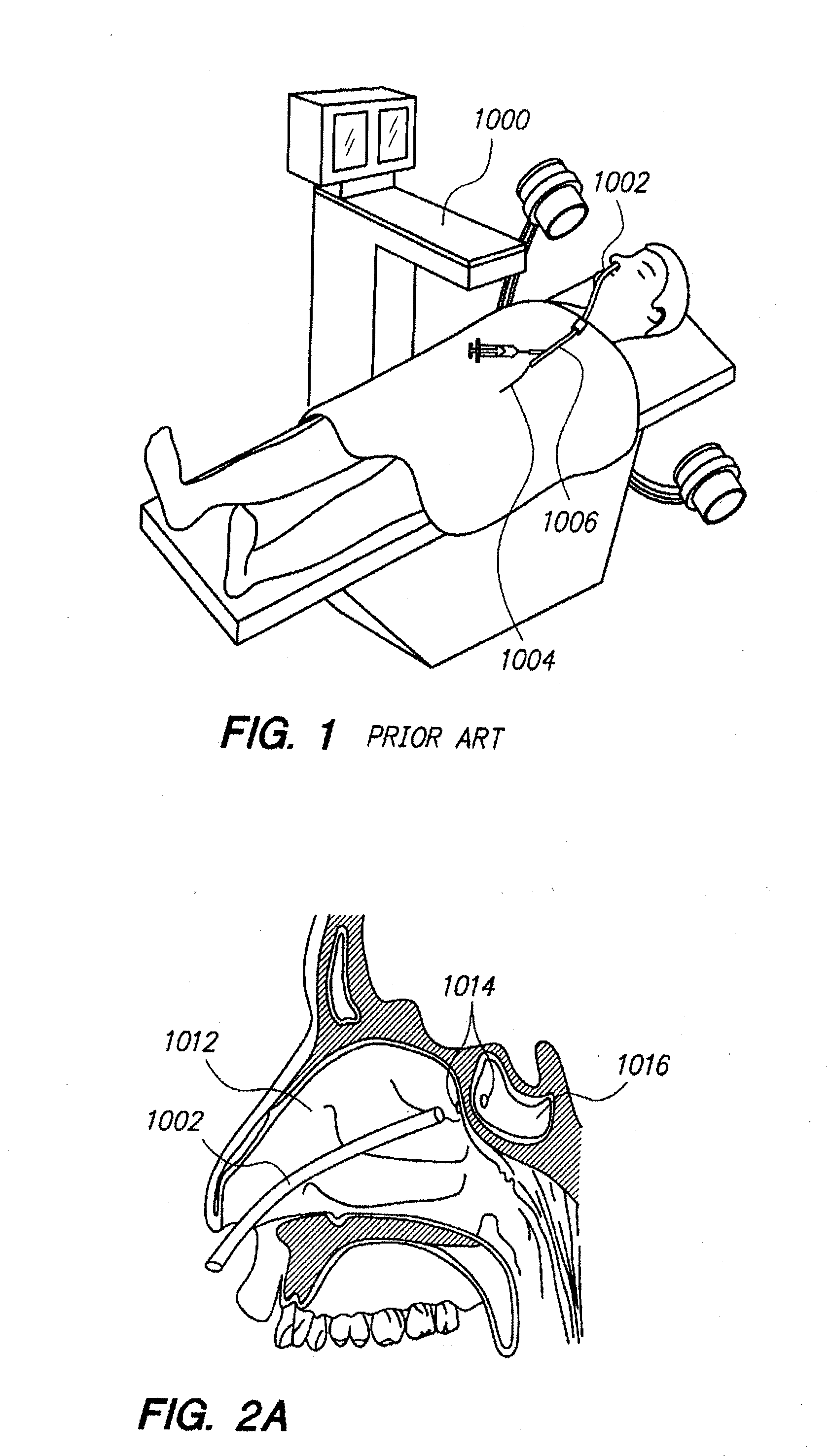
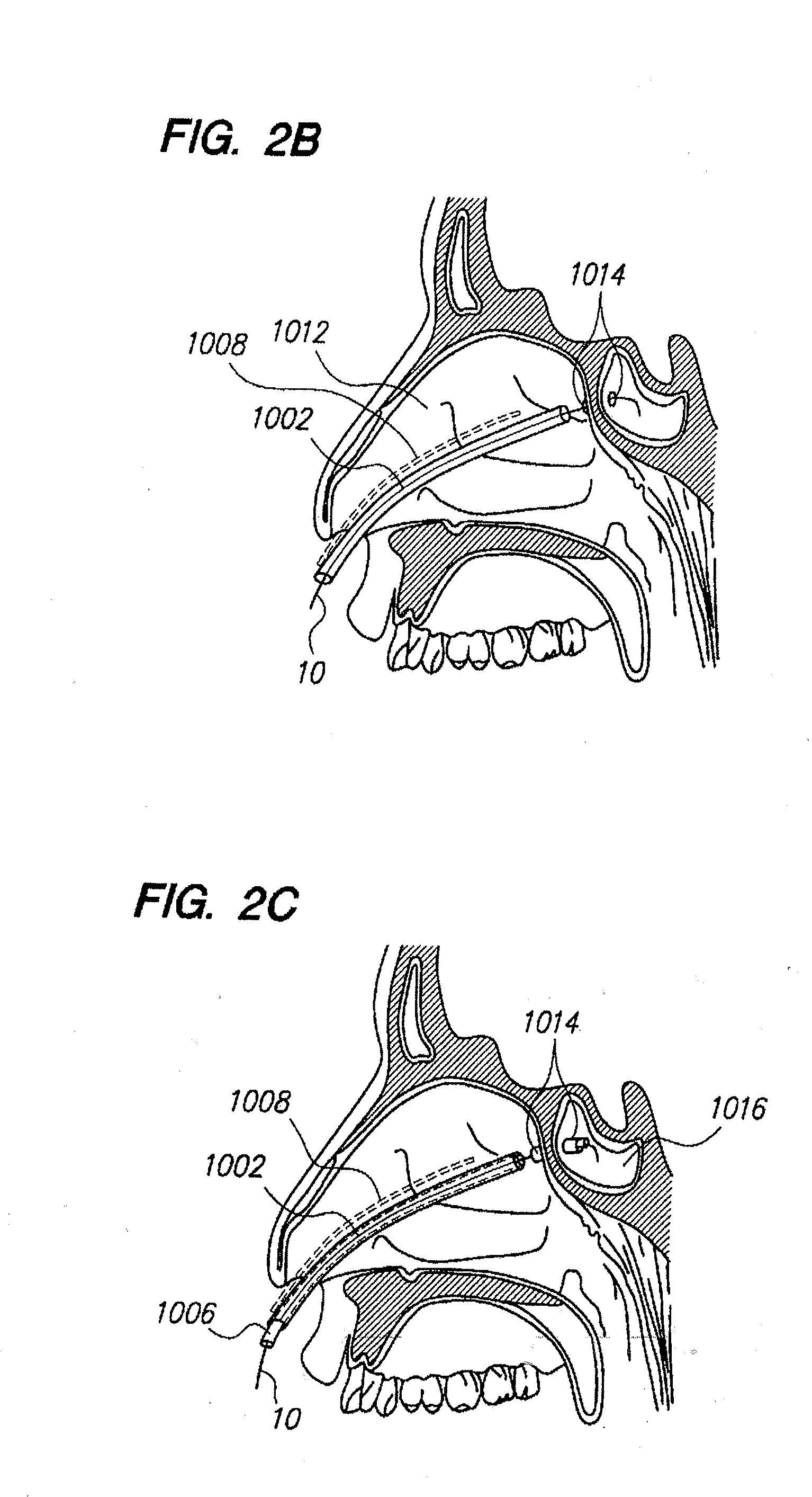
[0178]The present disclosure provides an apparatus and method which eliminates or reduces a need for remote imaging techniques. To accomplish this, there is disclosed a medical device having desirable pushability and torquability so that an interventional site is accessed. The disclosed medical device embodies structure or includes components which are pre-treated so that it can accommodate forces applied thereto during operation.

[0179]Before the present devices and methods are described, it is to be understood that this invention is not limited to particular embodiments described, as such may, of course, vary. It is also to be understood that the terminology used herein is for the purpose of describing particular embodiments only, and is not intended to be limiting, since the scope of the present invention will be limited only by the appended claims.

[0180]Where a range of values is provided, it is understood that each intervening value, to the tenth of the unit of the lower limit u...


PUM


Abstract

An illuminating wire medical device may include an elongate flexible housing and an illuminating fiber and a core wire extending through at least part of the housing, the core wire providing desired pushability and torquability. The illuminating device may further include a connector assembly cooperating with the illuminating fiber to accommodate changes in length and to absorb forces applied during use of the device.

Description

CROSS-REFERENCE TO RELATED APPLICATIONS[0001]This application is a continuation-in-part of U.S. patent application Ser. No. 11 / 522,497, filed Sep. 15, 2006, which is herein incorporated by reference in its entirety.FIELD OF THE INVENTION[0002]The present invention relates generally to medical devices, systems and methods and more particularly to methods and devices for performing minimally invasive procedures that reduce the need to provide fluoroscopic or other radiographic visualization.BACKGROUND[0003]The skull contains a series of cavities known as paranasal sinuses that are connected by passageways. The paranasal sinuses include frontal sinuses, ethmoid sinuses, sphenoid sinuses and maxillary sinuses. The paranasal sinuses are lined with mucus-producing mucosal tissue and ultimately open into the nasal cavity. Normally, mucus produced by the mucosal tissue slowly drains out of each sinus through an opening known as an ostium. If the mucosal tissue of one of these passageways be...

Claims


Application Information

Patent Timeline
Patent Type & Authority Applications(United States)
IPC IPC(8): A61B6/00A61M25/01
CPCA61B1/00071A61B1/0008A61B1/00117A61B1/233A61B1/00128A61B5/411A61M25/0105A61B1/00126A61B5/0084A61M2210/0681A61B2017/246A61M2210/0618
Inventor JENKINS, THOMASGOLDFARB, ERICVO, TOM THANHWISTED, THOMAS J.
Owner ACCLARENT INC
Why Eureka
Try Eureka