Apparatus and method for use in positioning an anchor

Inactive Publication Date: 2006-02-28
BONUTTI SKELETAL INNOVATIONS +1
View PDF28 Cites 255 Cited by
  • Summary
  • Abstract
  • Description
  • Claims
  • Application Information

AI Technical Summary

Benefits of technology

[0006]A slot may extend between openings at opposite ends of the tubular outer member. During positioning of the anchor relative to body tissue, the slot facilitates visualization of the anchor by a surgeon. Stop surface

Problems solved by technology

Difficulty may be encountered in positioning the suture relative to the tubular member.
In addition, difficulty may be encountered in retaining the suture anchor in a desired position relative to the tubular member.
When the known suture anchor inserter apparatus is to be utilized to position a suture relative

Method used


Image

  • Apparatus and method for use in positioning an anchor
  • Apparatus and method for use in positioning an anchor
  • Apparatus and method for use in positioning an anchor

Examples


second embodiment

Inserter—Second Embodiment

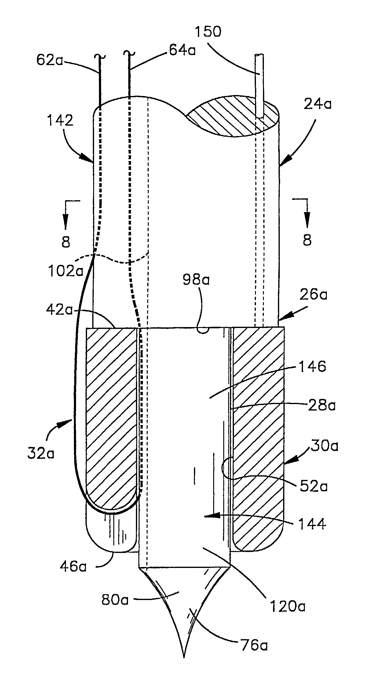
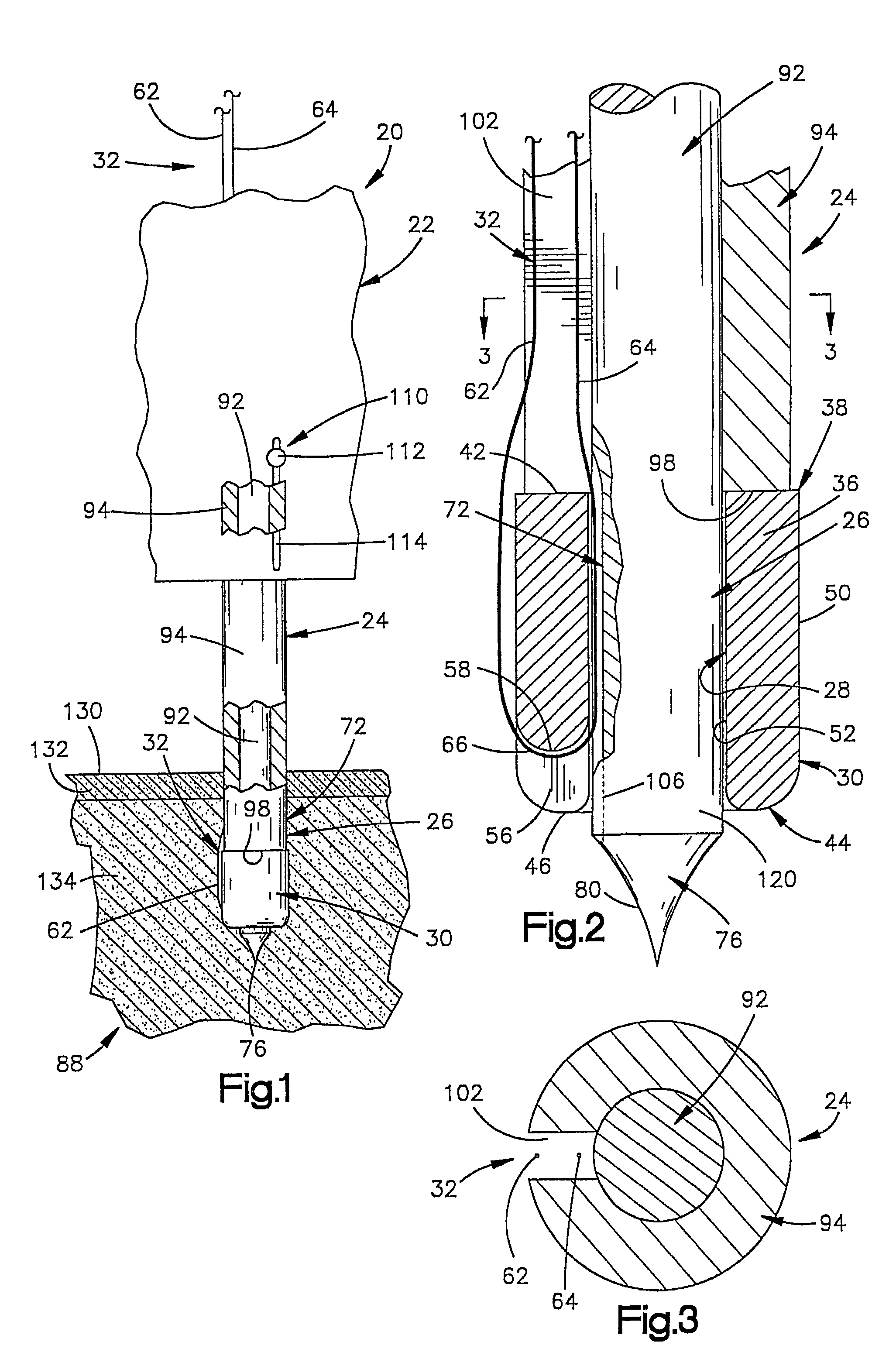
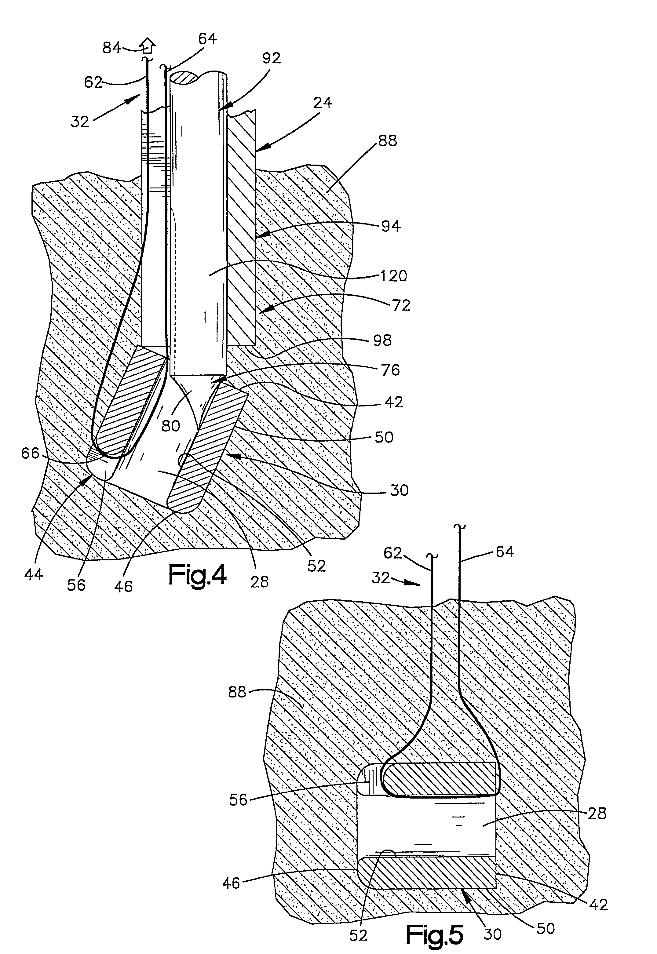
[0105]In the embodiment of the inserter or apparatus illustrated in FIGS. 1–5, the shaft 24 is formed by two members, that is, the inner member 92 and the outer member 94. In the embodiment of the inserter illustrated in FIGS. 6–9, the shaft of the inserter is formed by a single member. Since the embodiment of the invention illustrated in FIGS. 6–9 is generally similar to the embodiment of the invention illustrated in FIGS. 1–5, similar numerals will be utilized to designate similar components, the suffix letter “a” being associated with the numerals of FIGS. 6–9 to avoid confusion.

[0106]An anchor inserter 20a (FIG. 6) includes a manually engageable handle 22a and a one piece shaft 24a which extends outward from the handle. A leading end portion 26a of the one piece shaft 24a extends through a passage 28a in the anchor 30a. Since the illustrated anchor 30a is a suture anchor, a suture 32a extends through the passage 28a in the anchor and along the shaft 24a...

third embodiment

of Inserter

[0120]In the embodiments of the inserter illustrated in FIGS. 1–9, the anchor is retained on the shaft of the inserter prior to insertion of the anchor into body tissue. In the embodiment of the invention illustrated in FIG. 10, the inserter includes a spring which is utilized to retain the anchor on the shaft of the inserter. Since the embodiment of the invention illustrated in FIG. 10 is generally similar to the embodiments of the invention illustrated in FIGS. 1–9, similar numerals will be utilized to designate similar components, the suffix letter “b” being associated with the numerals of FIG. 10 to avoid confusion.

[0121]An inserter 20b (FIG. 10) includes a handle (not shown) and a shaft 24b which extends outward from the handle. The shaft 24b is integrally formed from a single piece of metal, that is, stainless steel. The shaft 24b includes a relatively large diameter main section 142b and a relatively small diameter leading end section 144b. The leading end section ...

fourth embodiment

Inserter—Fourth Embodiment

[0128]In the embodiments of the invention illustrated in FIGS. 1–10, the outer member 94 moves relative to the inner member 92 during positioning of an anchor relative to body tissue. In the embodiment of the invention illustrated in FIGS. 11–15, the inner member may move relative to the outer member. Since the embodiment of the invention illustrated in FIGS. 11–15 is generally similar to the embodiments of the invention illustrated in FIGS. 1–10, similar numerals will be utilized to identify similar components, the suffix letter “c” being added to the numerals of FIGS. 11–15 to avoid confusion.

[0129]An anchor inserter apparatus 20c, constructed in accordance with the present invention, is illustrated in FIG. 11 and is used to position an anchor 30c relative to body tissue. The illustrated anchor 30a is a suture anchor. The apparatus 20c includes a tubular outer member 94c. The tubular outer member 94c has a cylindrical tubular body 200 and a handle 22c whi...


PUM


Abstract

An apparatus for use in positioning an anchor includes a tubular outer member and an inner or pusher member. During use of the apparatus, a slot facilitates visualization of the position of the anchor relative to body tissue. An anchor retainer may be provided at one end of the tubular outer member to grip the anchor and hold the anchor in place during assembly. The anchor retainer also holds the anchor during movement of the apparatus from an assembly location to an operating room or other location where the apparatus is to be used. Indicia may be provided on the inner member to indicate the position of the anchor relative to body tissue. The tubular outer member may be utilized to guide a drill during formation of an opening in body tissue and may be subsequently utilized to guide movement of an anchor into the opening in the body tissue.

Description

RELATED APPLICATION[0001]This application is a divisional of U.S. patent application Ser. No. 09 / 766,728 filed Jun. 22, 2001 now U.S. Pat. No. 6,428,562. The aforementioned application Ser. No. 09 / 766,728 is itself a continuation of U.S. patent application Ser. No. 09 / 479,647 field Jan. 7, 2000, now U.S. Pat. No. 6,312,448. The aforementioned application Ser. No. 09 / 479,647 is itself a divisional of U.S. patent application Ser. No. 09 / 343,371 filed Jun. 30, 1999, now U.S. Pat. No. 6,003,430. The aforementioned application Ser. No. 09 / 343,371 is itself a divisional of U.S. patent application Ser. No. 09 / 022,351 filed Feb. 11, 1998, now U.S. Pat. No. 5,948,002. The aforementioned application Ser. No. 09 / 022,351 is itself a continuation-in-part of U.S. patent application Ser. No. 08 / 752,005 filed Nov. 15, 1996, now U.S. Pat. No. 5,814,072. The benefit of the earlier filing dates of the aforementioned U.S. patent applications has been and hereby is claimed.BACKGROUND OF THE INVENTION[00...

Claims


Application Information

Patent Timeline
IPC IPC(8): A61B17/04A61B17/00A61B17/17A61B17/34A61B19/00
CPCA61B17/0401A61B17/17A61B17/3468A61B17/1796A61B2019/462A61B2017/0409A61B2017/0417A61B2017/0496A61B2019/304A61B2017/00455A61B2090/034A61B2090/062
Inventor BONUTTI, PETER M.
Owner BONUTTI SKELETAL INNOVATIONS
Why Eureka
Try Eureka