Systems and methods for spinal fusion

a spinal cord and system technology, applied in the field of spinal cord surgery, can solve the problems of patient iliac crest, morbidity associated with autologous bone graft harvesting, and suffers in the use of autologous bone grafts, so as to promote overall bone fusion and promote fusion. , the effect of increasing the overall surface area

Active Publication Date: 2011-04-05
NUVASIVE
View PDF241 Cites 256 Cited by
  • Summary
  • Abstract
  • Description
  • Claims
  • Application Information

AI Technical Summary

Benefits of technology

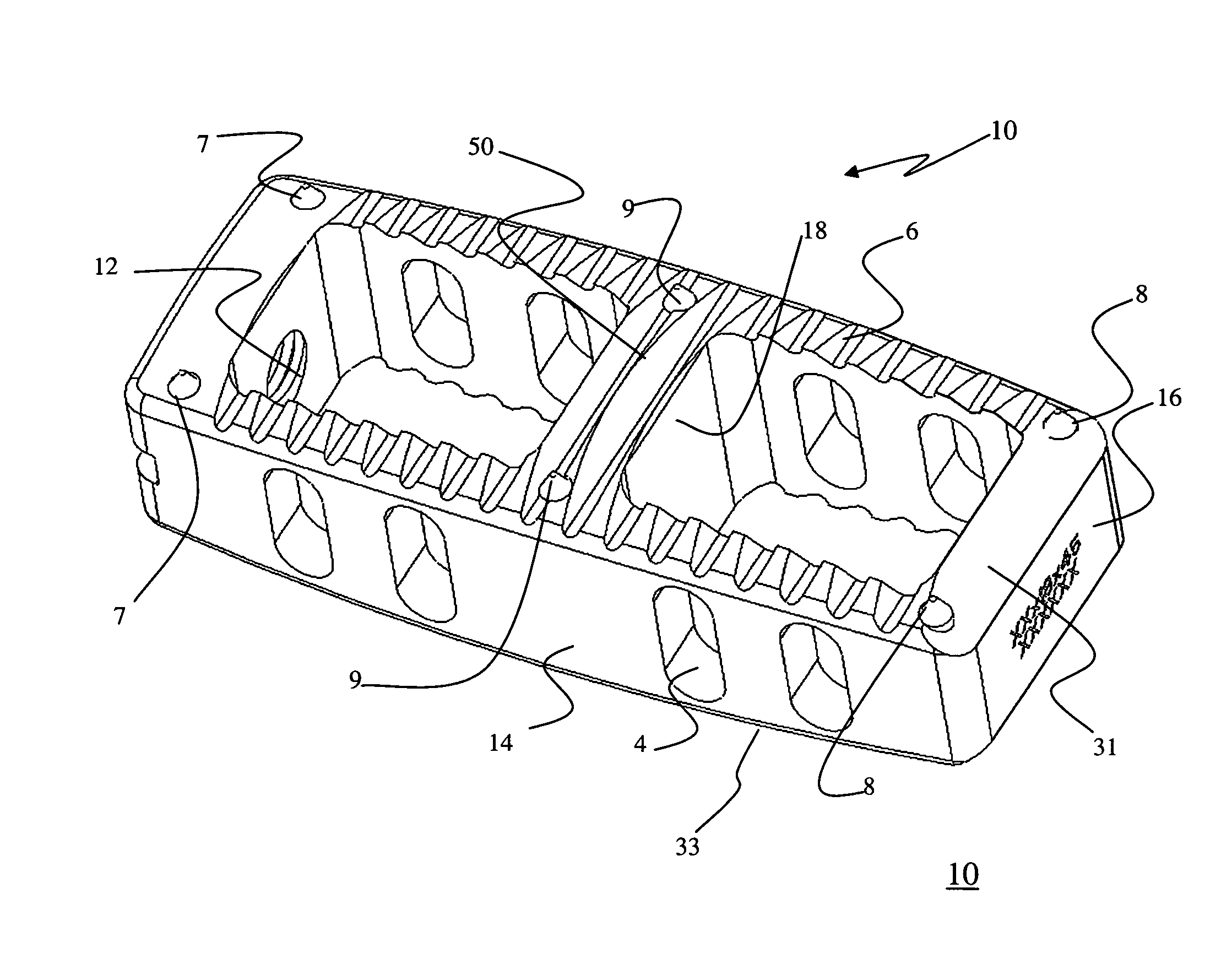
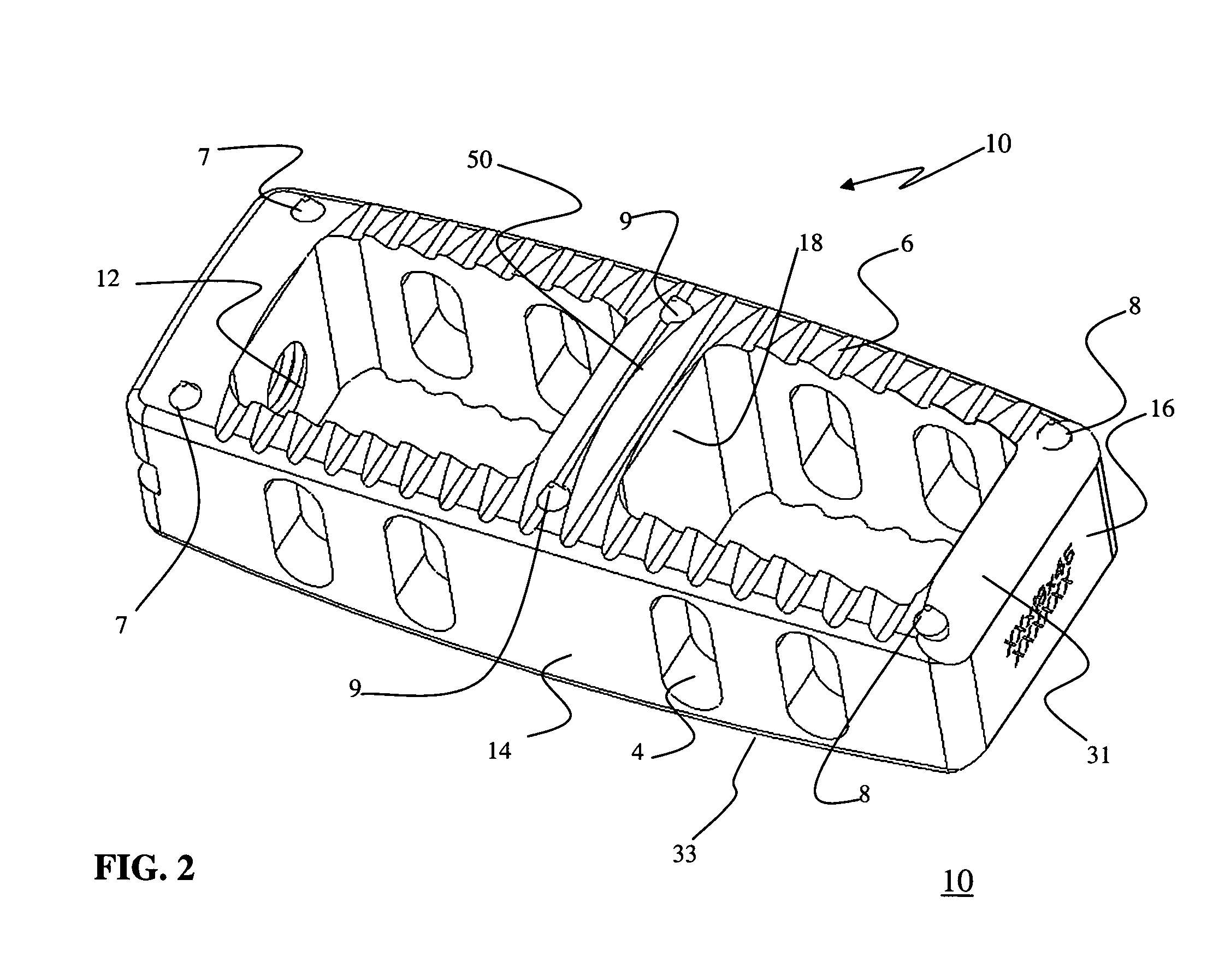
[0011]The spinal fusion implant of the present invention may be provided with any number of additional features for promoting fusion, such as apertures extending between the upper and lower vertebral bodies which allow a boney bridge to form through the spinal fusion implant of the present invention. Such fusion-promoting apertures may be dimensioned to receive any number of suitable osteoinductive agents, including but not limited to bone morphogenic protein (BMP) and bio-resorbable polymers, including but not limited to any of a variety of poly (D,L-lactide-co-glycolide) based polymers. The spinal fusion implant of the present invention is preferably equipped with one or more lateral openings which aid it provides in visualization at the time of implantation and at subsequent clinical evaluations.
[0012]The spinal fusion implant of the present invention may be provided with any number of suitable anti-migration features to prevent spinal fusion implant from migrating or moving from the disc space after implantation. Suitable anti-migration features may include, but are not necessarily limited to, angled teeth formed along the upper and / or lower surfaces of the spinal fusion implant and / or spike elements disposed partially within and partially outside the upper and / or lower surfaces of the spinal fusion implant. Such anti-migration features provide the additional benefit of increasing the overall surface area between the spinal fusion implant of the present invention and the adjacent vertebrae, which promotes overall bone fusion rates.
[0013]The spinal fusion implant of the present invention may be provided with any number of features for enhancing the visualization of the implant during and / or after implantation into a spinal target site. According to one aspect of the present invention, such visualization enhancement features may take the form of the spike elements used for anti-migration, which may be manufactured from any of a variety of suitable materials, including but not limited to a metal, ceramic, and / or polymer material, preferably having radiopaque characteristics. The spike elements may also take any of a variety of suitable shapes, including but not limited to a generally elongated element disposed within the implant such that the ends thereof extend generally perpendicularly from the upper and / or lower surfaces of the implant. The spike elements may each comprise a unitary element extending through upper and lower surfaces or, alternatively, each spike element may comprise a shorter element which only extends through a single surface (that is, does not extend through the entire height of the implant). In any event, when the spike elements are provided having radiodense characteristics and the implant is manufactured from a radiolucent material (such as, by way of example only, PEEK and / or PEKK), the spike elements will be readily observable under X-ray or fluoroscopy such that a surgeon may track the progress of the implant during implantation and / or the placement of the implant after implantation.
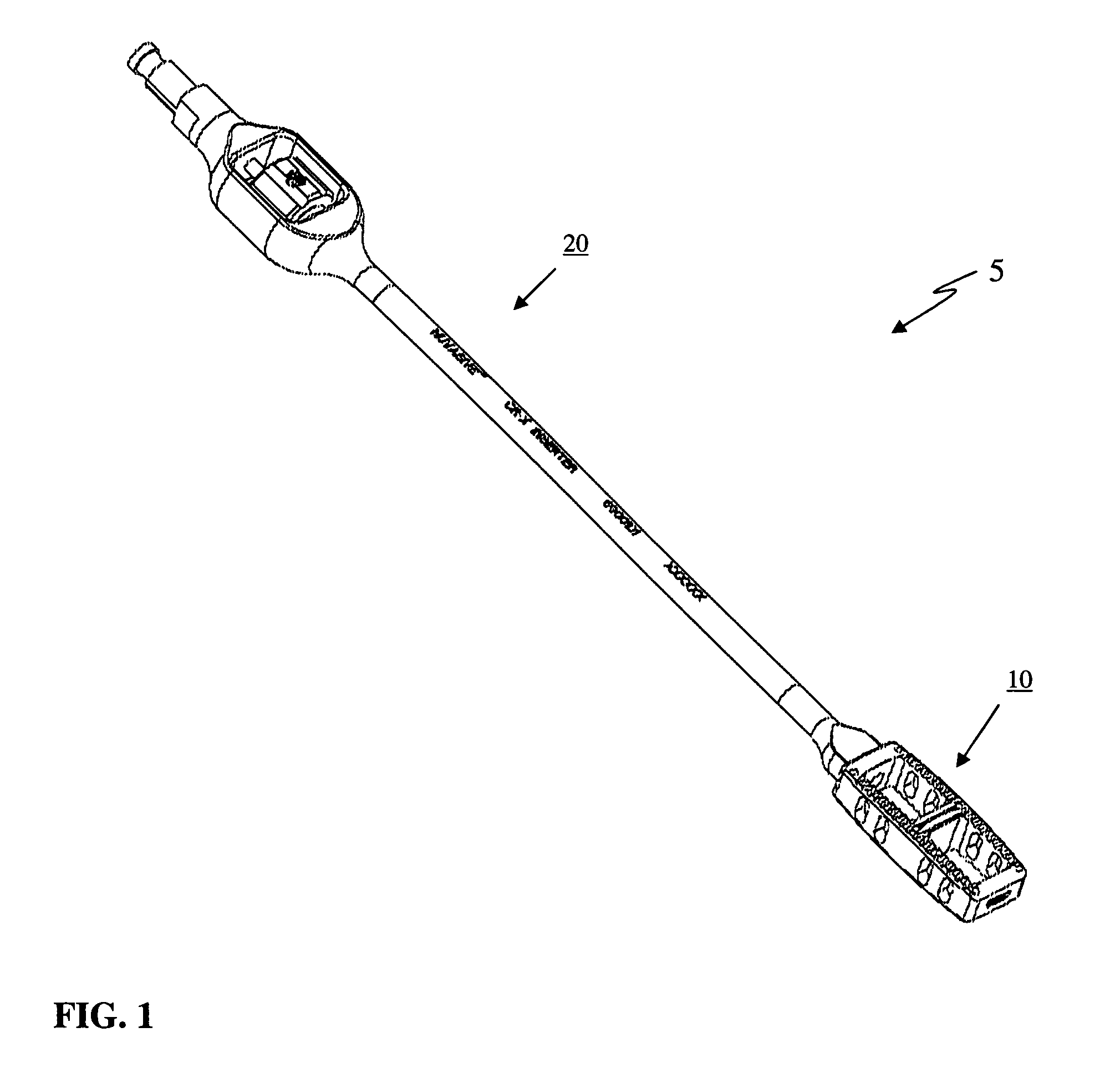
[0014]The spinal implant of the present invention may be introduced into a spinal target site through the use of any of a variety of suitable instruments having the capability to releasably engage the spinal implant. In a preferred embodiment, the insertion instrument permits quick, direct, accurate placement of the spinal implant of the present invention into the intervertebral space. According to one embodiment, the insertion instrument includes a threaded engagement element dimensioned to threadably engage into a receiving aperture formed in the spinal fusion implant of the present invention. According to another embodiment, the insertion instrument includes an elongate fork member and a generally tubular lock member.

Problems solved by technology

While generally effective, the use of autologous bone grafts suffers certain drawbacks.
A primary drawback is the morbidity associated with harvesting the autologous graft from the patient's iliac crest.
Another related drawback is the added surgical time required to perform the bone-harvesting.
While allograft bone grafts eliminate the morbidity associated with iliac crest bone harvesting, as well as decrease the overall surgical time, they still suffer certain drawbacks.
A primary drawback is supply constraint, in that the tissue banks that process and produce allograft bone implants find it difficult to forecast allograft given the inherent challenges in forecasting the receipt of cadavers.
Another related drawback is that it is difficult to manufacture the allograft with consistent shape and strength characteristics given the variation from cadaver to cadaver.

Method used


Image

  • Systems and methods for spinal fusion
  • Systems and methods for spinal fusion
  • Systems and methods for spinal fusion

Examples


Embodiment Construction

[0036]Illustrative embodiments of the invention are described below. In the interest of clarity, not all features of an actual implementation are described in this specification. It will of course be appreciated that in the development of any such actual embodiment, numerous implementation-specific decisions must be made to achieve the developers' specific goals, such as compliance with system-related and business-related constraints, which will vary from one implementation to another. Moreover, it will be appreciated that such a development effort might be complex and time-consuming, but would nevertheless be a routine undertaking for those of ordinary skill in the art having the benefit of this disclosure. The system to facilitate bone fusion and related methods disclosed herein boasts a variety of inventive features and components that warrant patent protection, both individually and in combination.

[0037]FIG. 1 illustrates, by way of example only, a spinal fusion system 5 for per...


PUM


Abstract

A system and method for spinal fusion comprising a spinal fusion implant of non-bone construction releasably coupled to an insertion instrument dimensioned to introduce the spinal fusion implant into any of a variety of spinal target sites.

Description

CROSS-REFERENCE TO RELATED APPLICATION[0001]This application claims the benefit of the filing date under 35 USC 119(e) of United States Provisional Application entitled “Systems and Methods for Spinal Fusion,” Ser. No. 60 / 557,536 filed Mar. 29, 2004, the entire contents of which are incorporated herein by reference.BACKGROUND OF THE INVENTION[0002]I. Field of the Invention[0003]The present invention relates generally to spinal surgery and, more particularly, to a system and method for spinal fusion comprising a spinal fusion implant of non-bone construction releasably coupled to an insertion instrument dimensioned to introduce the spinal fusion implant into any of a variety of spinal target sites.[0004]II. Discussion of the Prior Art[0005]Currently there are nearly 500,000 spine lumbar and cervical fusion procedures performed each year in the United States. Such procedures are commonly performed to correct problems, such as chronic back or neck pain, which result from degenerated in...

Claims


Application Information

Patent Timeline
Patent Type & Authority Patents(United States)
IPC IPC(8): A61F2/44
CPCA61F2/447A61F2/4611A61F2/4455A61F2/442A61F2/44A61F2220/0016A61F2/30767A61F2002/30265A61F2002/30266A61F2002/30593A61F2002/30617A61F2002/3082A61F2002/30904A61F2002/3093A61F2002/4615A61F2002/4629
Inventor CURRAN, MATTHEWPETERSON, MARK
Owner NUVASIVE
Why Eureka
Try Eureka