
Multiple-Input Multiple-Output Radio Transceiver

Inactive Publication Date: 2003-10-30
COGNIO
View PDF15 Cites 294 Cited by
  • Summary
  • Abstract
  • Description
  • Claims
  • Application Information

AI Technical Summary

Benefits of technology

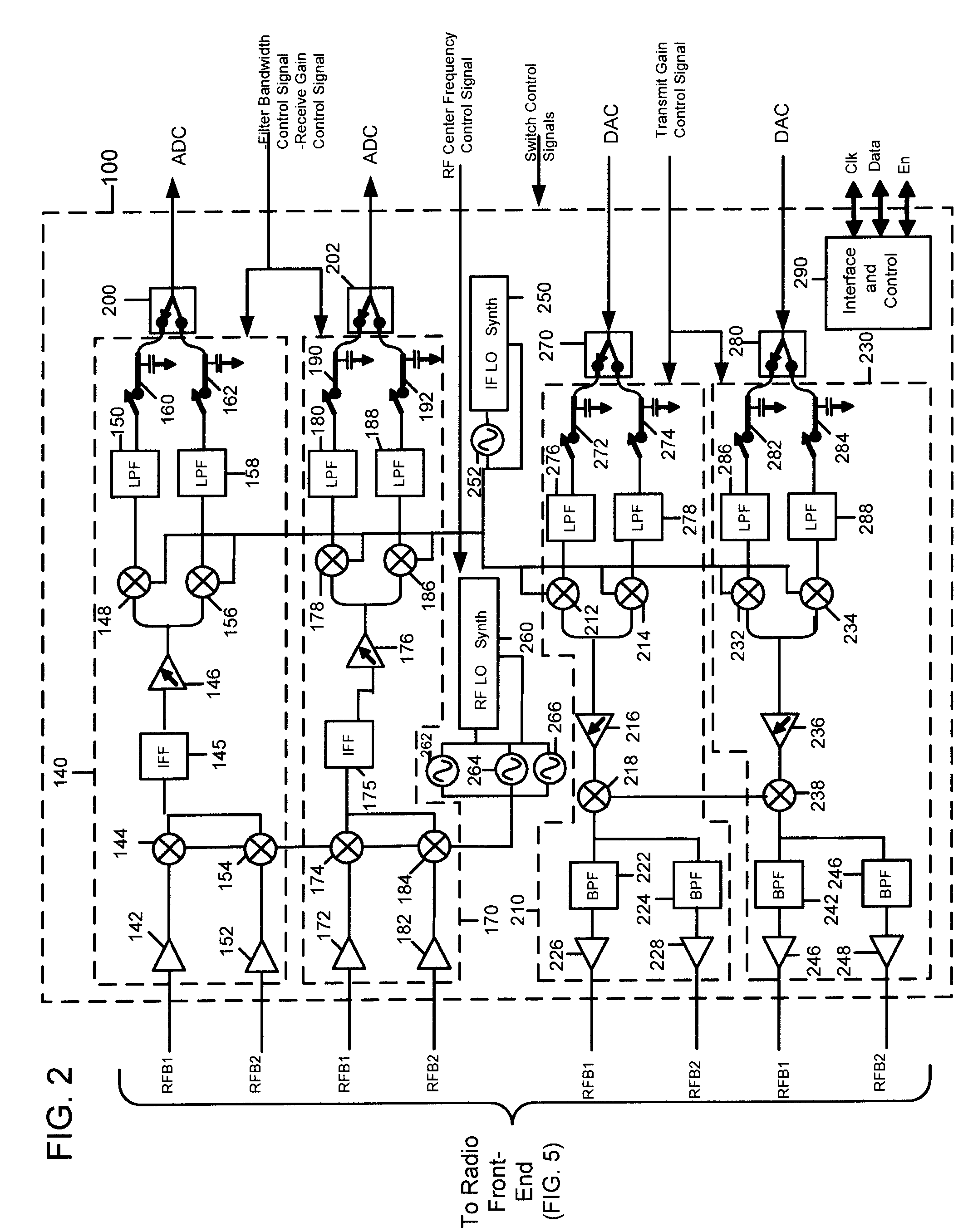
[0010] A MIMO radio transceiver is provided to support processing of multiple signals for simultaneous transmission via corresponding ones of a plurality of antennas and to support receive processing of multiple signals detected by corresponding ones of the plurality of antennas. The MIMO radio transceiver is one that is suitable for a highly integrated and low cost fabrication. In addition, the radio transceiver can perform MIMO transmit and receive operation in a portion of an RF band, up to substantially the entire RF band. The multiple transmit and receive paths are particularly useful to support joint maximal ratio combining techniques, also referred to herein as composite beamforming (CBF).
[0012] The multiple receive and transmit paths are integrated onto the same semiconductor integrated circuit. This provides significant cost and space / area savings. One use of this type of radio transceiver is to receive and transmit signals that, at baseband, are processed using the aforementioned CBF techniques (whereby weighted components of a signal are sent via each of a plurality of antennas and received at the other device by one or more antennas) to enhance the link margin with another communication device. In such an application, it is very important that each of the receive processing paths and each of the transmit processing paths be matched in terms of amplitude and phase response. Because the multiple receive and transmit paths are integrated into a single semiconductor die, the processing paths will inherently be better phase and amplitude matched, and any effects resulting from semiconductor integration will track among the processing paths. Moreover, any operational changes due to temperature variations will also better track among the processing paths because they are integrated into the same semiconductor integrated circuit.

Problems solved by technology

However, prior efforts to exploit the benefits of a MIMO system have failed because, among other reasons, a cost-effective MIMO radio could not be developed.

Method used


Image

  • Multiple-Input Multiple-Output Radio Transceiver
  • Multiple-Input Multiple-Output Radio Transceiver
  • Multiple-Input Multiple-Output Radio Transceiver

Examples


Embodiment Construction

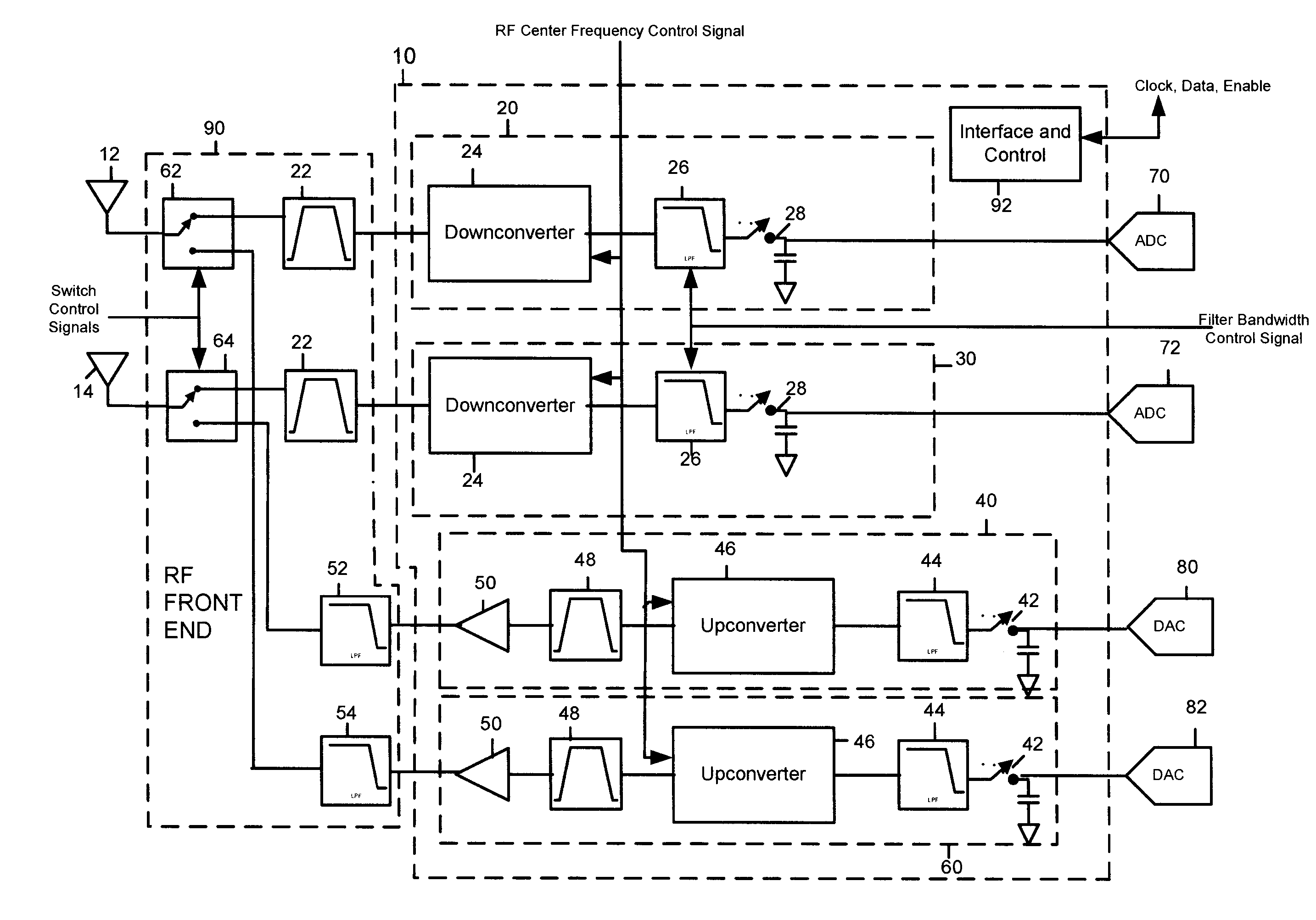
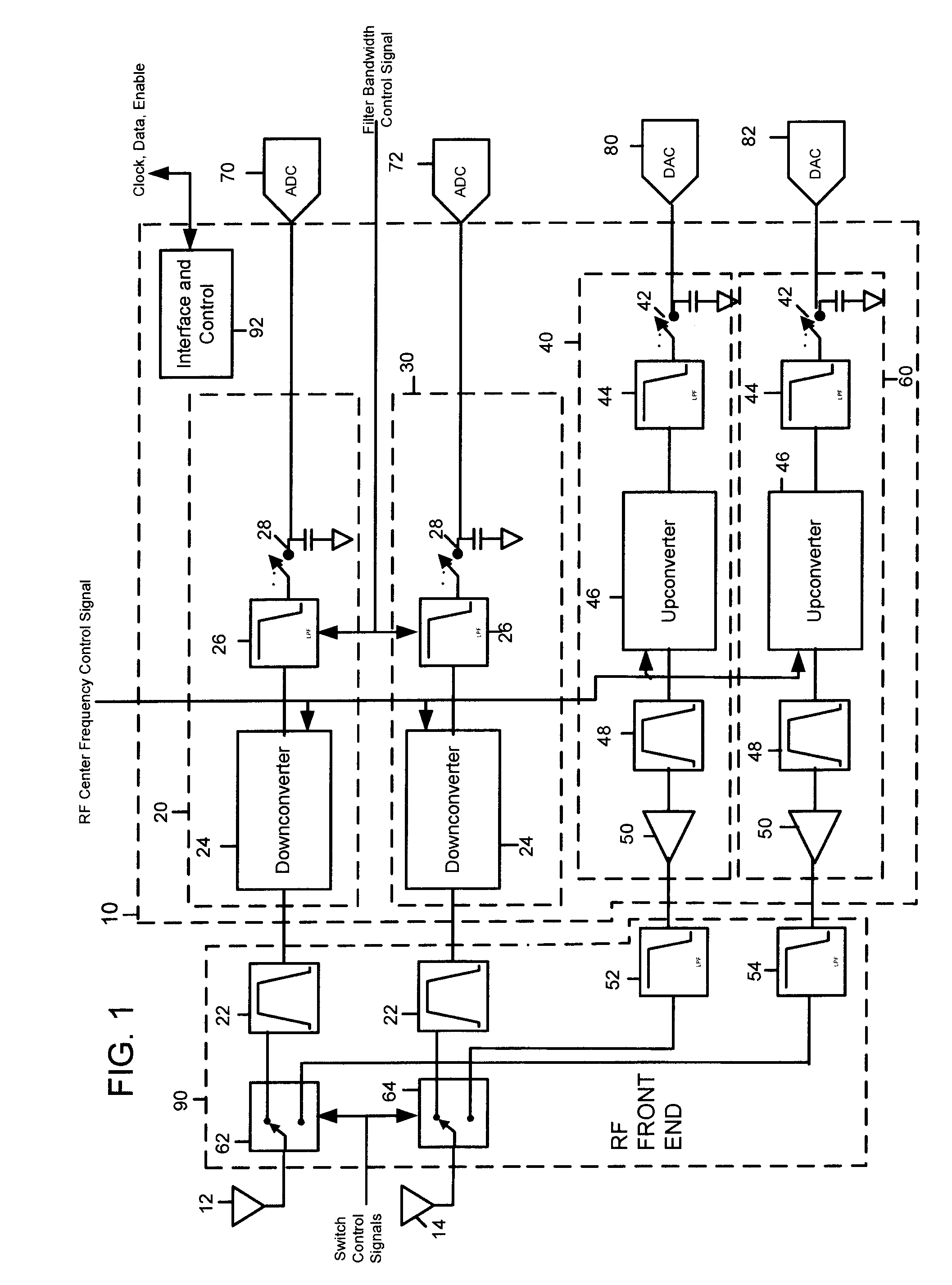
[0025] FIG. 1 shows a block diagram of a radio transceiver 10. The radio transceiver 10 is suitable for processing radio frequency signals detected by at least two antennas. The foregoing description is directed to an embodiment with two antennas 12 and 14, and an associated transmit and receive path for each, but this same architecture can be generalized to support in general N processing paths for N-antennas. This radio transceiver architecture is useful to support the aforementioned CBF techniques. CBF systems and methods are described in U.S. Patent Application No. 10 / 164,728, filed June 19, 2002 entitled "System and Method for Antenna Diversity Scheme Using Joint Maximal Ratio Combining"; U.S. Patent Application No. 10 / 174,689, filed June 19, 2002, entitled "System and Method for Antenna Diversity Using Equal Gain Joint Maximal Ratio Combining"; and U.S. Patent Application No. 10 / 064,482, filed July 18, 2002 entitled "System and Method for Joint Maximal Ratio Combining Using Ti...


PUM


Abstract

Abstract of Disclosure A MIMO radio transceiver to support processing of multiple signals for simultaneous transmission via corresponding ones of a plurality of antennas and to support receive processing of multiple signals detected by corresponding ones of the plurality of antennas. The radio transceiver provides, on a single semiconductor integrated circuit, a receiver circuit or path for each of a plurality of antennas and a transmit circuit or path for each of the plurality of antennas. Each receiver circuit downconverts the RF signal detected by its associated antenna to a baseband signal. Similarly, each transmit path upconverts a baseband signal to be transmitted by an assigned antenna.

Description

Background of Invention[0001] This application claims priority to the following U.S. Provisional Patent Applications (the entirety of each of which is incorporated herein by reference):[0002] Application No. 60 / 374,531, filed April 22, 2002;[0003] Application No. 60 / 376,722, filed April 29, 2002;[0004] Application No. 60 / 319,336, filed June 21, 2002;[0005] Application No. 60 / 319,360, filed June 27, 2002; and[0006] Application No. 60 / 319,434, filed July 30, 2002.[0007] The present invention relates to a multiple-input multiple-output (MIMO) radio transceiver.[0008] A primary goal of wireless communication system design is to use the available spectrum most efficiently. Examples of techniques to increase spectral efficiency include coded modulation techniques such as turbo codes and trellis-coded modulation, and multiple access techniques such as code division multiple access (CDMA).[0009] Yet another way to optimize spectral efficiency that has recently become popular in the academic...

Claims


Application Information

Patent Timeline
IPC IPC(8): H03D7/14H04B1/40
CPCH04B1/005H04B1/0057H03D2200/0025H04B1/406H03D7/165H04B1/006
Inventor SUGAR , GARY L.MASUCCI , ROBERT M.RAHN , DAVID G.
Owner COGNIO
Learn More