
3D Printed Mechanical Testing Device for Micro-Scale Material Specimens

Active Publication Date: 2021-08-26
UNITED STATES OF AMERICA
View PDF8 Cites 0 Cited by
  • Summary
  • Abstract
  • Description
  • Claims
  • Application Information

AI Technical Summary

Benefits of technology

This patent describes a new method for measuring the strength of small systems using a controlled mechanical force. The method allows for adjusting the force range to suit different system strengths, and also allows for obtaining stress-strain curves for micro-scale systems in a range of forces. The analysis is done quickly, and the system is made using low-cost 3D printing methods. The method also includes using support beams to align the specimen and reduce loads during handling. Overall, the method provides a reliable and efficient way to measure the strength of small systems.

Problems solved by technology

These systems are designed for specimens in the mm thickness range and typical force measurements >1 N. They are composed of expensive components, and commercially available systems require proprietary software for interfacing with the test system.
These test apparatuses have component sizes in the nm-μm range and require costly, time consuming processes for fabrication.
These fabrication methods are expensive and require specialized machining centers.

Method used


Image

  • 3D Printed Mechanical Testing Device for Micro-Scale Material Specimens
  • 3D Printed Mechanical Testing Device for Micro-Scale Material Specimens
  • 3D Printed Mechanical Testing Device for Micro-Scale Material Specimens

Examples


Embodiment Construction

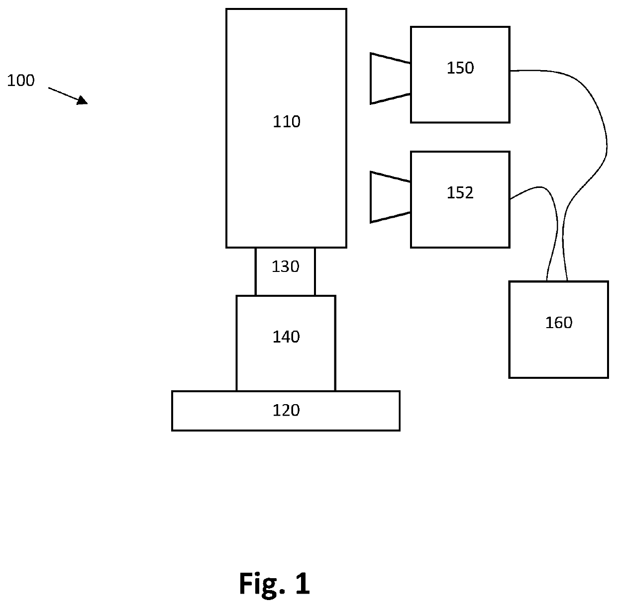
[0028]An exemplary testing system 100 is shown in FIG. 1, and includes a 3D printed mechanical testing fixture 110, a stage 120 with linear actuator 130 and controller 140, two cameras 150, 152, a data-acquisition system 160, and the specimen of interest (not shown). The mechanical testing device 110 is mounted in a vertical fashion with the upper end fixed (force sensor side) and the lower end attached to an actuator for providing the mechanical displacement. Performing the mechanical test in a vertical position provides for self-alignment of the device. A two camera system is used for data acquisition during testing. Camera 1 is focused on the specimen of interest and provides digital image correlation (DIC) strain measurements of the specimen during testing. Tracking markers are utilized by any appropriate means including—e.g., application of droplets of glue to the specimen, pen marks, or focused ion beam, etc.—which provides actual strain irrespective of potential compliance at...


PUM


Abstract

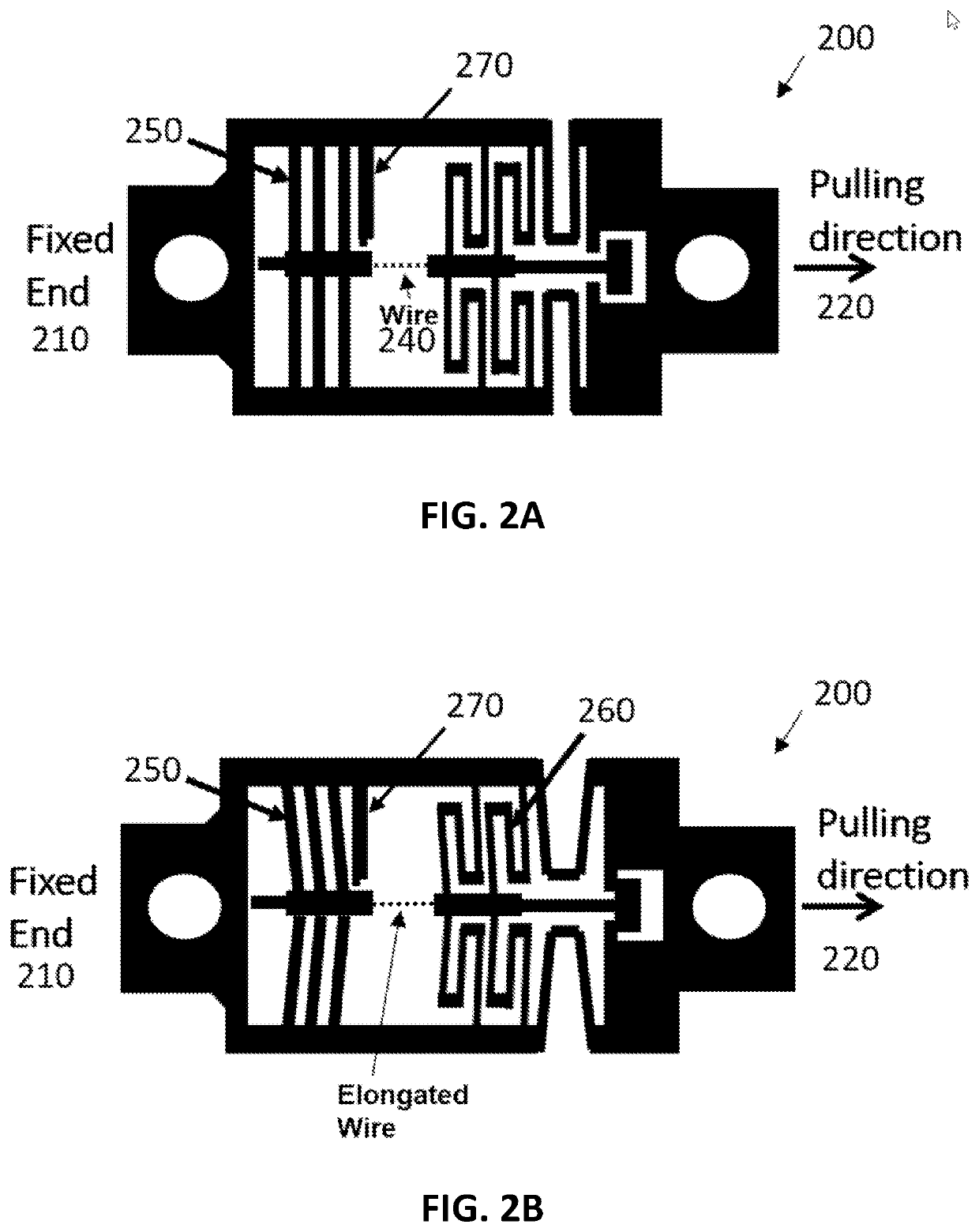
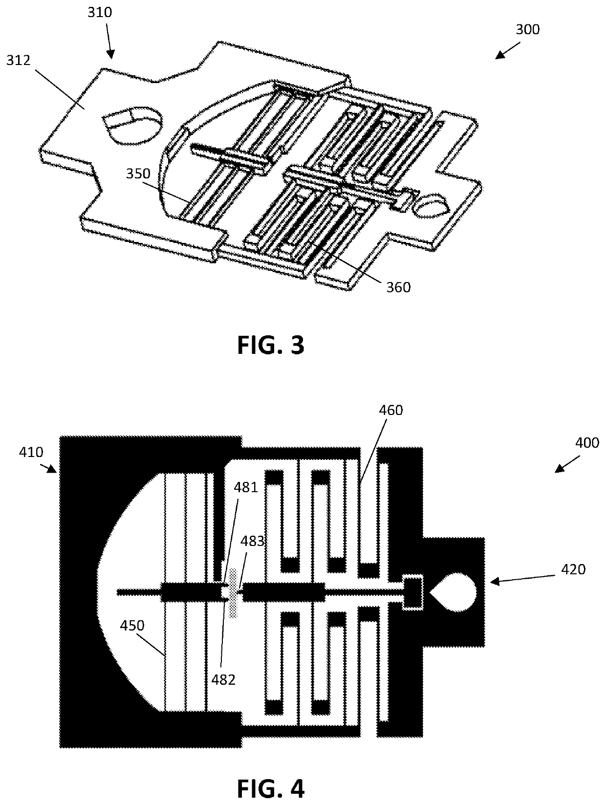
A system for mechanical testing a specimen includes a 3D printed mechanical testing fixture; a linear actuator having an axis of movement; a controller configured to control the linear actuator; two cameras; a data-acquisition system configured to acquire data from the linear actuator, the controller, and the two cameras; and the specimen. The specimen is marked in two locations with tracking markers to provide indication to the data acquisition system via at least one camera of movement and change in length of the specimen. The fixture includes force-sensing beams extending perpendicular to the axis of force

Description

RELATED APPLICATIONS[0001]This application claims the benefit of U.S. Provisional Application No. 62 / 980,788 filed Feb. 24, 2020, which is hereby incorporated herein by reference.FEDERALLY-SPONSORED RESEARCH AND DEVELOPMENT[0002]The United States Government has ownership rights in this invention. Licensing inquiries may be directed to Office of Technology Transfer, US Naval Research Laboratory, Code 1004, Washington, D.C. 20375, USA; +1.202.767.7230; techtran@nrl.navy.mil, referencing NC 112456.FIELD OF INVENTION[0003]The present invention relates generally to mechanical testing, and more particularly to 3d printed mechanical testing systemsBACKGROUND[0004]The conventional tension test subjects a sample to a controlled tension until failure. Directly measurable mechanical properties include ultimate tensile strength, breaking strength, maximum elongation, and reduction in area. Typical mechanical test systems consist of specimen fixturing systems (cross heads), with one interacting ...

Claims


Application Information

Patent Timeline
IPC IPC(8): G01B11/16G01L1/24
CPCG01B11/16G01L1/24G01N3/08G01N3/068G01B11/165G01N2203/0647G01N2203/0298
Inventor KANG, WONMORUDOLF, CHRISTOPHER
Owner UNITED STATES OF AMERICA
Learn More