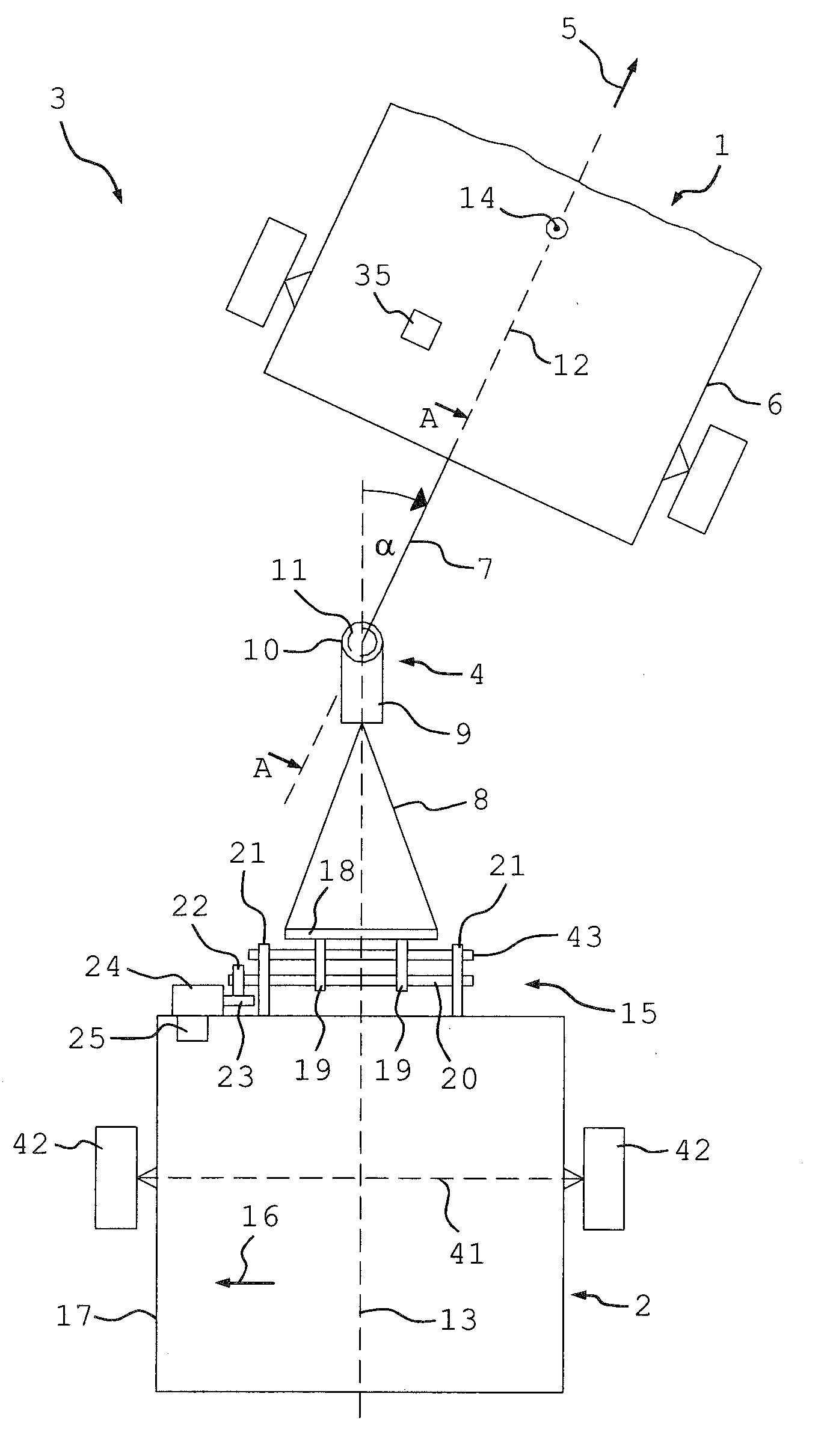
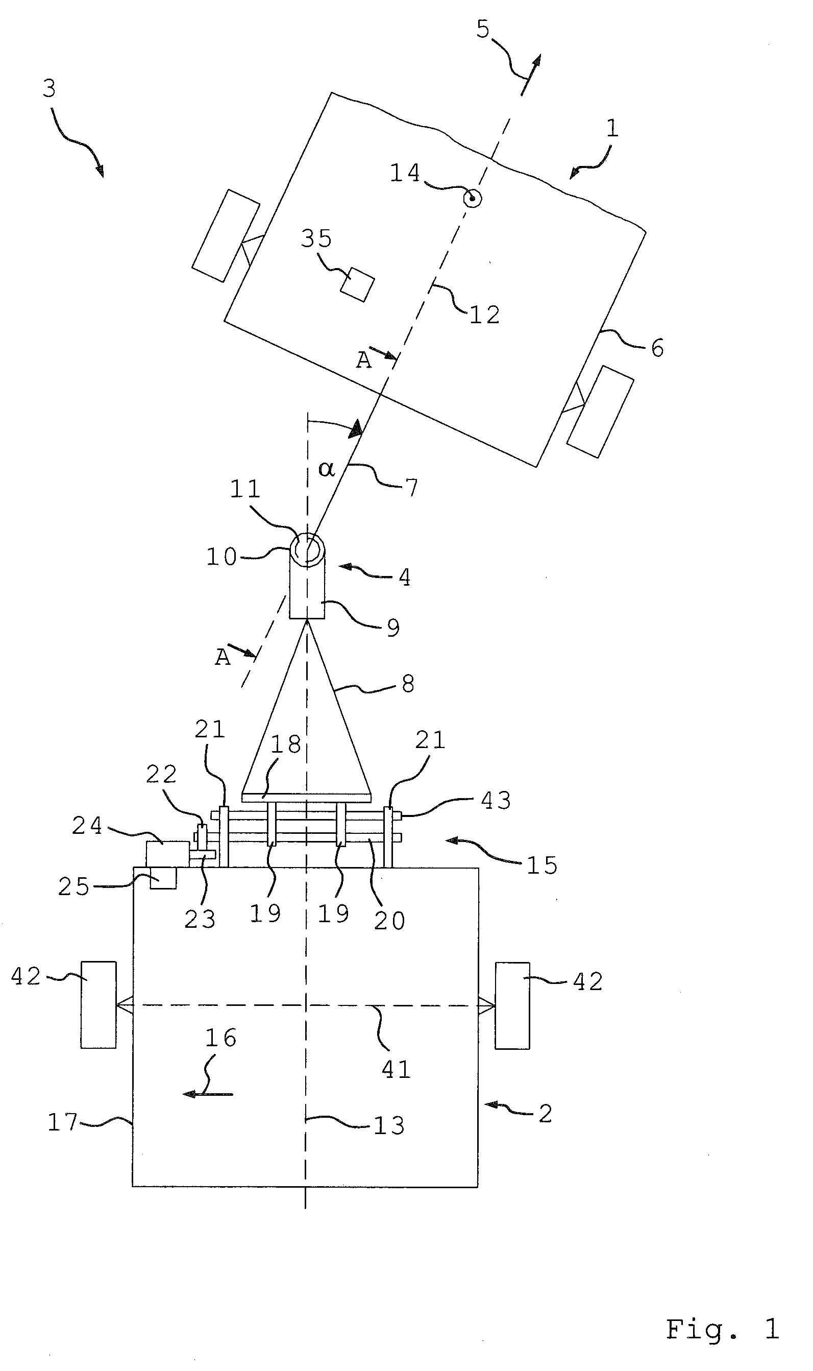
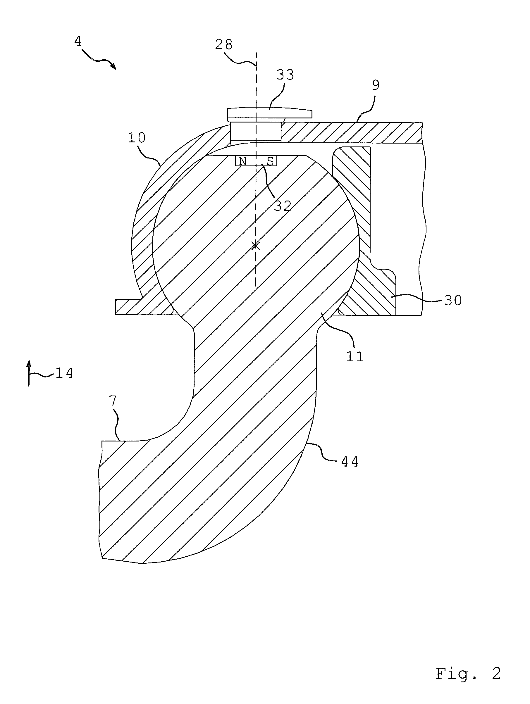
[0028]FIG. 1 shows a top view on a combination 3 formed of a tractor 1 and a trailer 2, wherein the tractor 1 is connected with the trailer 2 by way of a trailer coupling 4 in an articulated fashion. The reference symbol 5 indicates the conventional forward travel direction of the tractor 1. The trailer coupling 4 includes a coupling member 7 which is rigidly connected with the chassis 6 of the tractor and a coupling lock 9 which is attached to the hitch 8 of the trailer 2. The coupling lock 9 includes a ball socket 10, in which a schematically illustrated hitch ball 11 arranged on the rearward end of the coupling member 7 is located, as viewed in the travel direction 5. The coupling lock 9 also forms a forward end of the hitch 8, as viewed in the travel direction 5.
[0029]The angle α between the longitudinal axis 12 of the tractor 1 and the longitudinal axis 13 of the trailer 2 forms the so-called articulation angle of the composition 3. The articulation angle α is, in particular, located in a plane perpendicular to the vertical vehicle direction 14 of the tractor 1, wherein the vertical vehicle direction 14 in FIG. 1 extends perpendicular to the drawing plane.
[0030]The hitch 8 is supported on the chassis 17 of the trailer 2 for displacement in the transverse direction 16 of the trailer 2 and can be moved in the transverse direction 16 with a spindle drive 15. The hitch 8 has at its rearward end, as viewed in the direction of travel 5, a carriage 18, on which retaining members 19 are attached, which are screwed onto the spindle 20. In addition, the retaining members 19 are arranged on a guide 43 for displacement in the transverse direction 16, wherein the guide 43 is supported by bearings 21 attached on the chassis 17 which absorb forces transverse to the spindle axle. The spindle 20 is supported on the chassis 17 for rotation about its longitudinal axis by the bearings 21. A gear wheel 22 is non-rotatably connected with the spindle 20 and meshes with a worm 23 that can be driven by an electric motor 24. The gear wheel 22 and the worm 23 therefore form a worm gear. The electric motor 24 is attached on the chassis 17 and can be controlled by a controller 25 provided on the trailer 2. When the motor 24 is controlled by the controller 25 to turn the worm 23, the spindle 20 is rotated about its longitudinal axis by the intervening gear wheel 22. Because the longitudinal axis of the spindle 20 extends in the transverse direction 16, the retaining members 19 are moved by the rotating spindle 20 in the transverse direction 16 and displace the carriage 18 and hence the hitch 8 relative to the chassis 17 in the transverse direction 16. This changes the articulation angle α.
[0031]The hitch 8 can be displaced relative to the chassis 17 back-and-forth in the transverse direction, meaning in the direction of the arrow 16 and in the opposite direction. The direction of the displacement of the hitch 8 in the transverse direction can therefore be controlled with the controller 25.
[0032]The trailer 2 has a non-steerable vehicle axle 41 extending in the transverse direction 16 with two wheels 42 and is in this embodiment constructed as a single-axle trailer. Alternatively, the trailer 2 may also have several vehicle axles.
[0033]FIG. 2 shows schematically a side view of the trailer coupling 4 along the longitudinal axis 12 and in the vertical vehicle direction 14, wherein the hitch ball 11 is rigidly connected with the coupling member 7. The hitch ball 11 is located at the end of a section 44 of the coupling member 7 which is curved upwardly in the direction of the vertical axis 14 and is formed as a single piece therewith. Alternatively, the hitch ball 11 may also be manufactured separate from the coupling member 7 and attached thereto, for example by a welded connection.
[0034]The hitch ball 11 sits in the ball socket 10, which is rotatable relative to the hitch ball 11 about a vertical axis 28. The vertical axis 28 extends here in the vertical direction 14 of the tractor 1. In addition, the hitch ball 11 is axially secured in the hitch ball joint by an actuatable lock 30. The term “axial” refers here to the direction of the vertical axis 28. A rotation of the coupling lock 9 relative to the hitch ball 11 about the vertical axis 28 thus describes the articulation angle α.
[0035]The upper end face of the hitch ball 11 is flattened and has a recess in which a permanent magnet 32, which is rigidly connected with the hitch ball 11, is arranged. The North Pole N and the South Pole S of the magnet 32 are indicated to illustrate its magnetization which extends perpendicular to the vertical axis 28. A magnetic field-sensitive sensor 33, which is spaced from the magnet 32, is attached on the coupling lock 9 above the magnet 32. A rotation of the magnet 32 relative to the coupling lock 9 about the vertical axis 28 can be detected with the magnetic field-sensitive sensor 33. The signal 34 supplied by the sensor 33 (see FIG. 3) has therefore information about the articulation angle α.
[0036]FIG. 3 shows schematically the controller 25, which is electrically connected with the motor 24. The magnetic field-sensitive sensor 33 is also electrically coupled with a controller 25 and supplies to the controller 25 the signal characterizing the actual actuation angle α. In addition, the controller 25 is electrically connected with an acquisition device 35 arranged in the tractor 1, which supplies a direction signal 36 to the controller 25. The acquisition device 35 includes a steering wheel angle sensor 37 which is arranged on the steering shaft 38 of the steering wheel 39 of the tractor 1. The direction signal 36 has therefore information about the actual steering wheel angle of the tractor 1, from which a travel direction desired by the operator can be deduced.
[0037]When the tractor 1 travels in the reverse direction, i.e., opposite the forward direction 5, the controller 25 evaluates the direction signal 36 to obtain a desired articulation angle α′, which will be referred to as nominal articulation angle. The controller 35 determines from the signal 34 the actual articulation angle α, which is referred to as actual articulation angle. The controller 25 computes from these two angles the difference Δα (Δα=α′−α) as a measure for the deviation between the nominal articulation angle α′ and the actual articulation angle α. Because the articulation angle α can be changed by operating the motor 24, which causes a transverse displacement of the hitch 8, the controller 25 controls the motor 24 with an electric current 40 based on the deviation Δα so as to reduce the absolute magnitude of the deviation Δα. The goal is here to minimize the deviation Δα or to reduce it to zero. The controller hence operates as a regulator. In this way, the trailer 2 can be stabilized during reverse travel in accordance with the direction desired by the operator of the tractor 1.
[0038]FIG. 4 shows a schematic cross-sectional view of a modified trailer coupling 4, which can replace the trailer coupling illustrated in FIG. 2. Features which are identical or similar for both trailer couplings are indicated with identical reference symbols, corresponding to the trailer coupling in FIG. 2.
[0039]A ball pin 27, which includes the hitch ball 11 and a pin 26, is supported in a housing 29 by a rotary bearing 31 for rotation about the vertical axis 28. The housing 29 is arranged at the end of the coupling member 7 and is formed as a single piece therewith. The hitch ball 11 sits in the ball socket 10 and is axially secured in the ball socket 10 by the actuatable lock 30. Because for a rotation about the vertical axis 28, the friction between the hitch ball 11 and the coupling lock 9 is significantly greater than the friction of the rotary bearing 31, rotation of the coupling lock 9 relative to the hitch ball 11 about the vertical axis 28 is prevented by friction. A rotation of the coupling lock 9 relative to the housing 29 about the vertical axis 28 therefore describes the articulation angle α.
[0040]A permanent magnet 32, which can rotate together with the ball pin 26 about the vertical axis 28 relative to the housing 29, is rigidly secured on the lower end face of the pin 26. A magnetic field-sensitive sensor 33, which is arranged below and spaced from the magnet 32, is secured on the housing 29, by which a rotation of the magnet 32 relative to the housing 29 about the vertical axis 28 can be measured. The signal 34 supplied by the sensor 33 therefore has information about the articulation angle α.