This helps you quickly interpret patents by identifying the three key elements:
Problems solved by technology
Method used
Benefits of technology
[0006]The presently disclosed visual indicator mechanism and surgical stapling device including such a visual indicator mechanism is provided to afford a clinician greater visualization of the movement of an anvil assembly in relation to a cartridge assembly after the anvil and cartridge assemblies have been approximated to within a firing zone, i.e., the zone of approximation in which the anvil head and staple cartridge are in close enough approximation to allow for the proper formation of staples against the anvil assembly. The visual indicator mechanism improves visualization of the di
Problems solved by technology
Due to the small size of the staples being fired and, thus, the limited size of the firing zone, it can be difficult for a clinician to accur
Method used
Image
Click on the blue label to locate the original text in one second.
Reading with bidirectional positioning of images and text.
Examples
Embodiment Construction
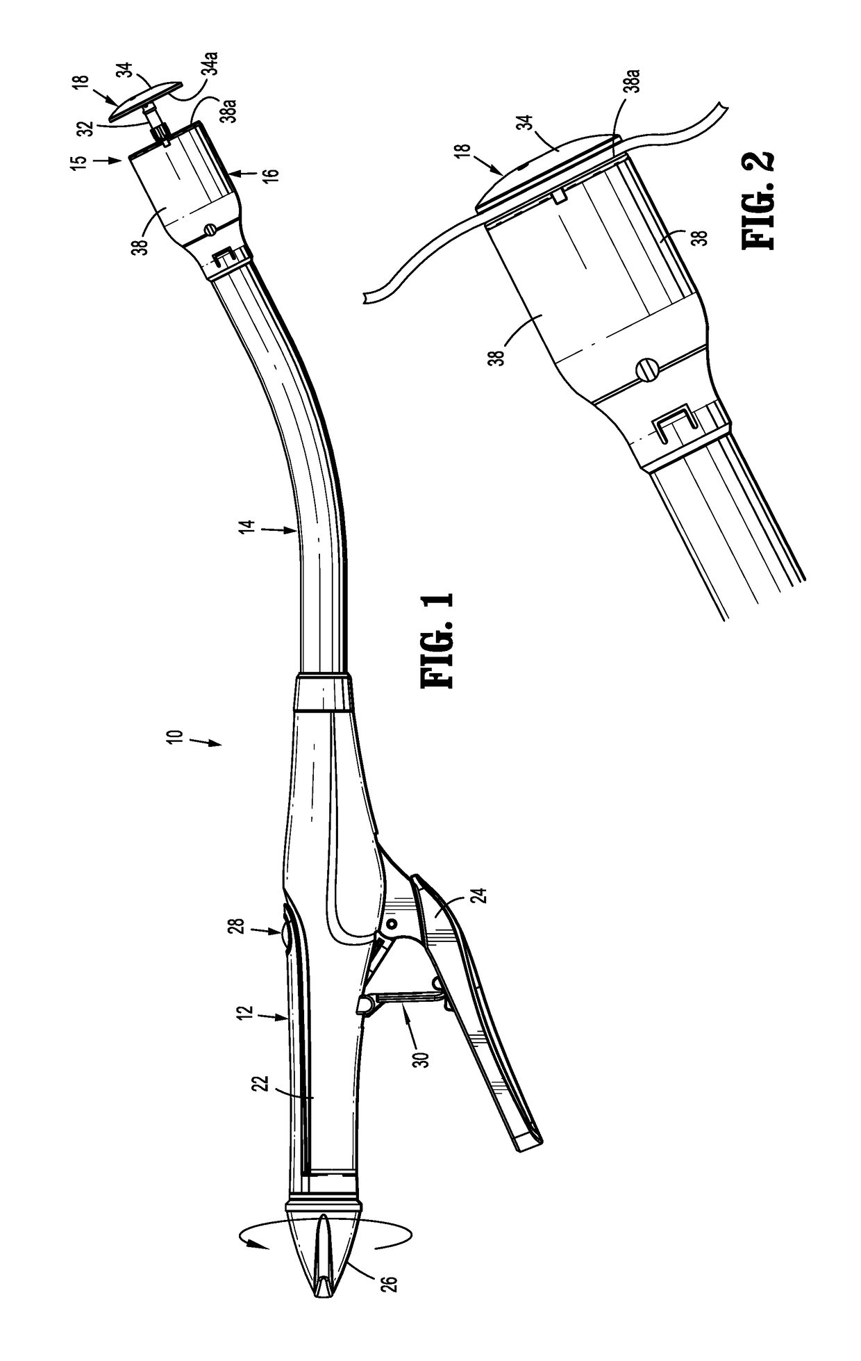
[0034]A surgical stapling device including embodiments of the presently disclosed visual indicator mechanism will now be described in detail with reference to the drawings in which like reference numerals designate identical or corresponding elements in each of the several views. In this description, the term “proximal” is used generally to refer to the portion of the device that is closer to a clinician, while the term “distal” is used generally to refer to the portion of the device that is farther from the clinician. In addition, the term “endoscopic” is used generally to refer to procedures including endoscopic, laparoscopic, and arthroscopic performed through a small incision or a cannula inserted into a patient's body. Finally, the term clinician is used generally to refer to medical personnel including doctors, nurses, and support personnel.
[0035]The presently disclosed visual indicator mechanism is provided to afford a clinician greater visualization of the movement of an anv...
PUM
Abstract
A surgical stapling device includes a visual indicator mechanism that provides a clinician with greater visualization of the movement of an anvil assembly in relation to a cartridge assembly after the anvil and cartridge assemblies have been approximated to within a firing zone. The visual indicator mechanism improves visualization of the different degrees of approximation within the firing zone by providing an indicator cover having spaced slots that allow indicia formed on an indicator member to sequentially appear within the spaced slots to identify the different degrees of approximation within the firing zone.
Description
BACKGROUND1.Technical Field[0001]The present disclosure relates to surgical stapling devices, and more particularly, to circular stapling devices that include visual indicator mechanisms for indicating when the surgical stapling device is in a fire-ready zone.2. Background of Related Art[0002]Anastomosis is the surgical joining of separate hollow organ sections. In known circular anastomosis procedures, two ends of organ sections are joined by means of a surgical stapling device that drives a circular array of staples through each organ section and simultaneously cores any tissue interior of the driven circular array of staples to free a tubular passage. Examples of such devices are described in U.S. Pat. Nos. 7,234,624, 6,945,444, 6,053,390, 5,568,579, 5,119,983, 4,646,745, 4,576,167, and 4,473,077, the content of each of which is incorporated herein by reference in its entirety.[0003]Typically, a circular stapling device has an elongated shaft having a handle portion supported at ...
Claims
Application Information
Patent Timeline
Application Date:The date an application was filed.
Publication Date:The date a patent or application was officially published.
First Publication Date:The earliest publication date of a patent with the same application number.
Issue Date:Publication date of the patent grant document.
PCT Entry Date:The Entry date of PCT National Phase.
Estimated Expiry Date:The statutory expiry date of a patent right according to the Patent Law, and it is the longest term of protection that the patent right can achieve without the termination of the patent right due to other reasons(Term extension factor has been taken into account ).
Invalid Date:Actual expiry date is based on effective date or publication date of legal transaction data of invalid patent.