Device for equipping a hole in a panel, and panel thus equipped

Inactive Publication Date: 2005-06-09
AIRBUS OPERATIONS (SAS)
View PDF12 Cites 11 Cited by
  • Summary
  • Abstract
  • Description
  • Claims
  • Application Information

AI Technical Summary

Problems solved by technology

It would seem however that this reinforcement entails a complicated operation, especially when stiffeners (separated from one another in practice by a gap of about 20 centimeters) are present at the position of the reinforcement.
Besides, once this reinforcement is made, the equipping of the hole, especiall

Method used


Image

  • Device for equipping a hole in a panel, and panel thus equipped
  • Device for equipping a hole in a panel, and panel thus equipped
  • Device for equipping a hole in a panel, and panel thus equipped

Examples


Embodiment Construction

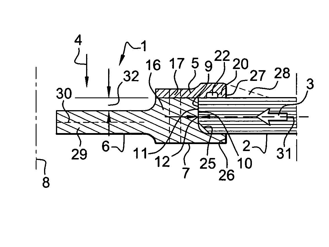
[0023]FIG. 1a shows a device for the equipping of a hole according to the invention. This device is designed to equip a hole 1 made in a panel 2. The panel 2 is a panel of any unspecified structure; in particular, the panel 2 is a panel made of composite material for an aircraft. The panel 2, in the invention, is liable to be subjected to a compression force 3 in the plane of the panel. The direction of the force 3 is substantially perpendicular to a direction 4 of the hole 1. At most, a divergence of a few degrees may arise owing to a slight buckling of the panel 2. In the invention, the device for equipping the hole 1 comprises at least one first detachable plate 5 and a flange 6 that occupies the hole 1. In a preferred variant, the plate 6 is fixedly joined with a fin 7 used to hold the panel 2 clamped, but without any excessive compression. It is also possible to envisage making the fin 7 detachably, like the plate 5.

[0024] In one example, the plate 5, the flange 6 and / or the i...


PUM

PropertyMeasurementUnit
Forceaaaaaaaaaa
Ratioaaaaaaaaaa
Deformation enthalpyaaaaaaaaaa

Abstract

A removable plate and a flange that occupies a hole in a panel. The flange has the particular feature of taking up compressive force to which the panel is subjected in its plane, perpendicularly to the hole. The weight of the device used to equip the hole is reduced, and the mechanical behavior of the panel at the position of the hole is improved.

Description

RELATED APPLICATION [0001] This application claims priority to French Application No. 03 50975 filed Dec. 4, 2003. BACKGROUND OF THE INVENTION [0002] 1. Field of the Invention [0003] An object of the present invention is a device for fitting out or equipping a hole in a panel, especially an aircraft panel, although it can also be used in any other type of structure. It also pertains to a panel thus equipped. The invention seeks to help improve the performance of the panels provided with such holes, whether these holes are made because of an a priori requirement or because of subsequent repairs to the panel. [0004] For the building of structures, especially aircraft, it is the common practice to make panels which are typically panels for the wings and fuselage of an aircraft. For reasons of weight and mechanical hardness, the panels are generally made out of composite materials, typically sheets of carbon fiber and / or sheets of stratified material. In the structure into which this pa...

Claims


Application Information

Patent Timeline
IPC IPC(8): B29C73/10B64C1/14B64C3/00B64F5/00
CPCB29C73/10B64F5/0009B64C1/1446B64F5/10
Inventor FOURNIE, LUDOVICCABANAC, JEAN-PIERRELACOMBE, JEAN-CLAUDE
Owner AIRBUS OPERATIONS (SAS)
Why Eureka
Try Eureka