Backlight unit for a liquid crystal display device

a liquid crystal display device and backlight technology, applied in electric lighting, lighting and heating apparatus, instruments, etc., can solve problems such as uneven brightness on display screens, achieve the effects of reducing the number of components required, preventing uneven brightness, and improving the image quality of the liquid crystal display devi

Inactive Publication Date: 2005-06-16
FUNAI ELECTRIC CO LTD
View PDF5 Cites 14 Cited by
  • Summary
  • Abstract
  • Description
  • Claims
  • Application Information

AI Technical Summary

Benefits of technology

[0012] An object of the present invention is to provide such a backlight unit for a liquid crystal display device that can prevent unevenness of brightness on a display screen of the liquid crystal display device so as to improve the image quality of the liquid crystal display device, and makes it possible to reduce the number of components required therefor so as to reduce the cost.

Problems solved by technology

Generally, unevenness in brightness on the display screen is caused by higher brightness in the vicinity of each of the lamps.

Method used


Image

  • Backlight unit for a liquid crystal display device
  • Backlight unit for a liquid crystal display device
  • Backlight unit for a liquid crystal display device

Examples


Embodiment Construction

[0029] The best modes and preferred embodiments of the present invention will be described hereinafter with reference to the annexed drawings. The specific embodiments described are not intended to cover the entire scope of the present invention of the present invention, and hence the present invention is not limited to only the specific embodiments.

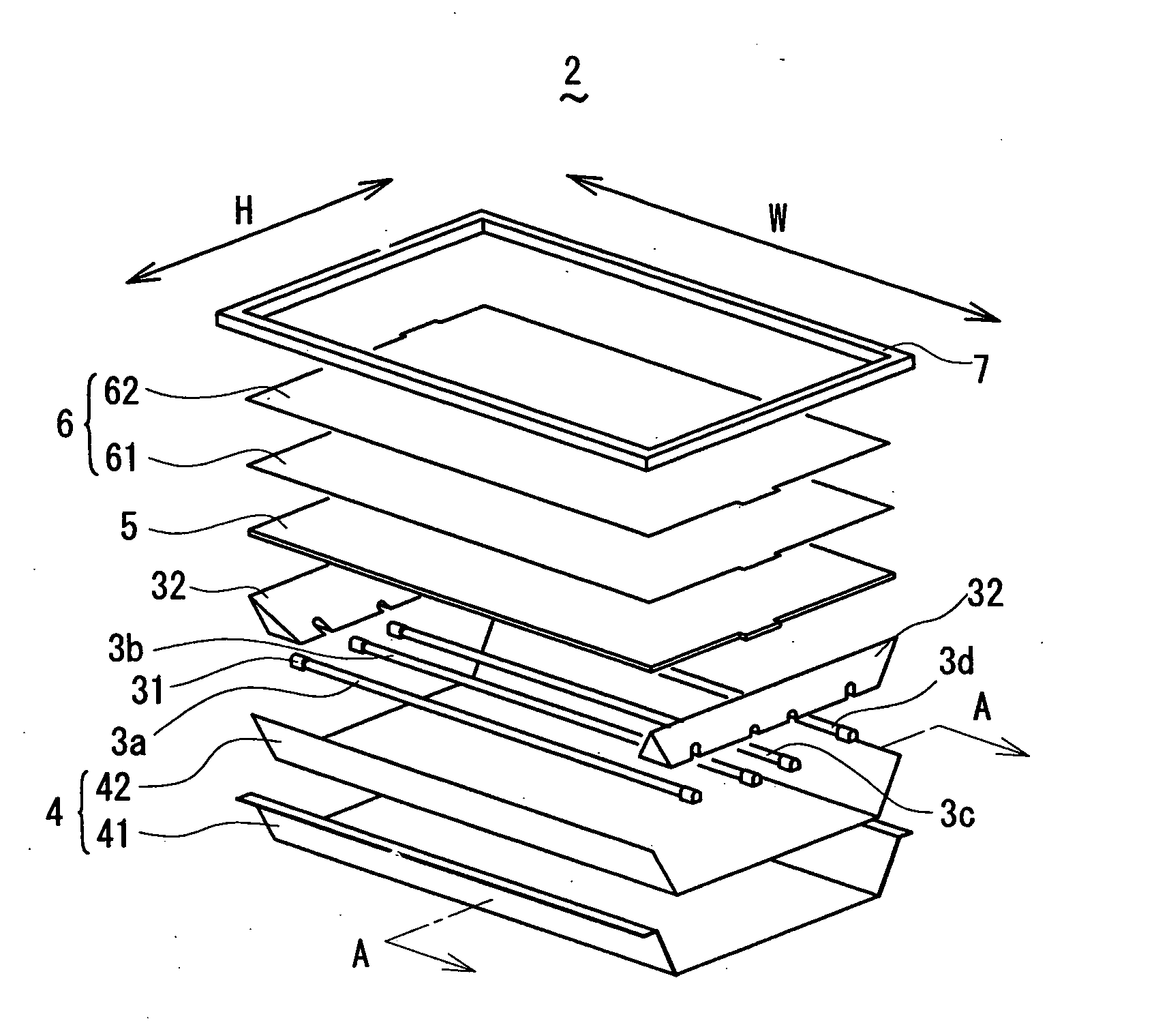
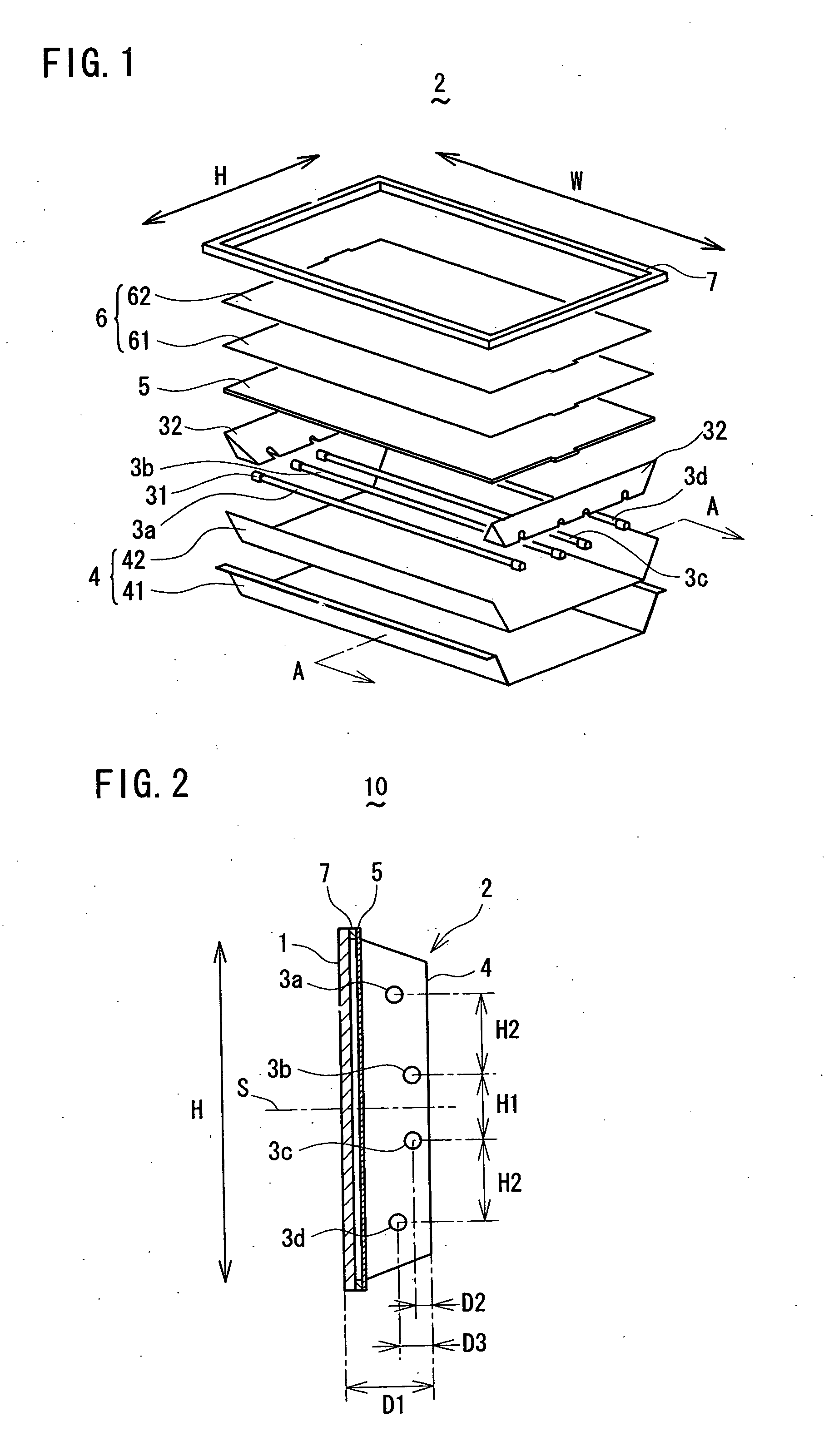
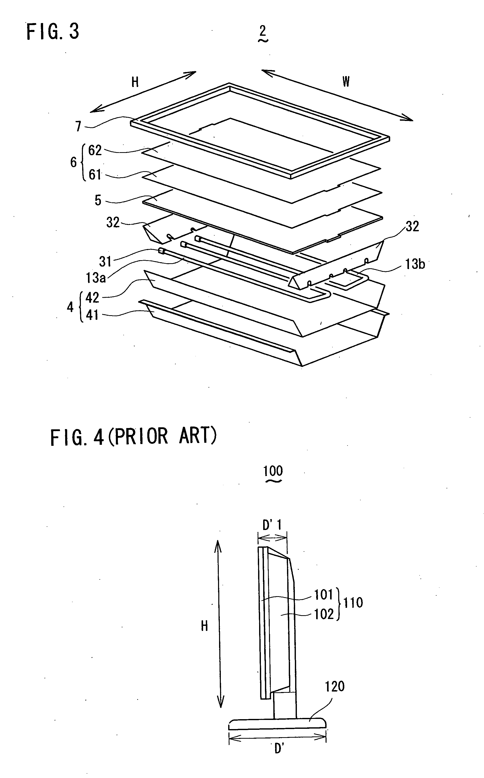
[0030]FIG. 1 and FIG. 2 show a backlight unit 2 according to a first embodiment of the present invention. The backlight unit 2 comprises: four straight tube type Cold Cathode Fluorescent Lamps (straight tube type lamps) 3a to 3d to illuminate a liquid crystal panel 1 from behind; a reflector plate 4 placed behind the Cold Cathode Fluorescent Lamps 3a to 3d and having a reflection surface to reflect light from the straight tube type Cold Cathode Fluorescent Lamps 3a to 3d; a diffuser plate 5 to diffuse the direct light from the straight tube type Cold Cathode Fluorescent Lamps 3a to 3d and the reflected light from the reflector plate 4 s...


PUM

PropertyMeasurementUnit
widthaaaaaaaaaa
heightaaaaaaaaaa
distanceaaaaaaaaaa

Abstract

Four straight tube type Cold Cathode Fluorescent Lamps are placed such that the distance from the two inner Cold Cathode Fluorescent Lamps to a reflection surface of a reflector plate is shorter than the distance from the two outer Cold Cathode Fluorescent Lamps to the reflection surface of the reflector plate, whereby it becomes possible to make the distance from the two inner Cold Cathode Fluorescent Lamps to a liquid crystal panel longer than the distance from the two outer Cold Cathode Fluorescent Lamps to the liquid crystal panel. Generally, unevenness in brightness on the display screen is caused by higher brightness in the vicinity of each of the Cold Cathode Fluorescent Lamps. Accordingly, by making longer the distance from the two inner Cold Cathode Fluorescent Lamps to the liquid crystal panel, it becomes possible to prevent unevenness in brightness at a central portion of the display screen, which is more likely to be noticed by users, thereby improving the image quality of the liquid crystal display device.

Description

BACKGROUND OF THE INVENTION [0001] 1. Field of the Invention [0002] The present invention relates to a backlight unit, and more particularly to a backlight unit of direct type to illuminate a liquid crystal panel of a liquid crystal display device from behind. [0003] 2. Description of the Related Art [0004] Liquid crystal display devices, which have advantages e.g. in space and energy savings, are becoming common in the prior art, replacing CRT (cathode ray tube) display devices. As shown in FIG. 4, a conventional liquid crystal display device 100 comprises a liquid crystal panel 101 to act as an electronic shutter and a backlight unit 102 to serve as a light source. The liquid display panel 101 controls the light transmission of light illuminated by the backlight unit 102 so as to display images. Note that in FIG. 4 and later described FIGS. 5 and 6 according to the prior art as well as FIGS. 1 through 3 according to the present invention, the height and width directions of a backl...

Claims


Application Information

Patent Timeline
Patent Type & Authority Applications(United States)
IPC IPC(8): F21S2/00G02F1/1335F21Y103/00F21Y103/37G02F1/1333G02F1/13357
CPCG02F2001/133613G02F1/133604G02F1/133613
Inventor TANAKA, MITSURU
Owner FUNAI ELECTRIC CO LTD
Why Eureka
Try Eureka