Led chip lamp apparatus

a technology of led chip and lamp, which is applied in the direction of lighting and heating apparatus, point-like light sources, semiconductor devices for light sources, etc., can solve the problems of reduced work effect of led chips, inability to effectively disperse high heat consequently shorten the lifetime so as to increase the lifetime and light-emitting efficiency of led chip lamp apparatus

Inactive Publication Date: 2005-08-04
HARVATEK CORPORATION
View PDF3 Cites 79 Cited by
  • Summary
  • Abstract
  • Description
  • Claims
  • Application Information

AI Technical Summary

Benefits of technology

[0007] It is therefore a secondary object of the invention to provide an LED chip lamp apparatus with increased lifetime and light-emitting efficiency.
[0008] To achieve the above objects, the present invention provides an LED chip lamp apparatus comprising a heat sink with a reflector, an LED lamp module and a heat pipe. The LED lamp module is assembled in an inside of the reflector for reflecting light of the LED lamp module. The heat pipe has two ends, one end thereof connecting to the LED lamp module and the other end thereof connecting to the heat sink for transmitting heat of the LED lamp module so as to conduct and disperse the heat produced from an LED chip and to increase the lifetime and the light emitting efficiency of the LED chip lamp apparatus.

Problems solved by technology

However, the high heat of the LED chip lamp apparatus can't be effectively dispersed and the work effect of the LED chips thus declines.
Furthermore, the LED chip lamp apparatus is used in a high heat state for a long time and the lifetime thereof is consequently shortened.

Method used


Image

  • Led chip lamp apparatus
  • Led chip lamp apparatus
  • Led chip lamp apparatus

Examples


Embodiment Construction

[0016] Wherever possible in the following description, like reference numerals will refer to like elements and parts unless otherwise illustrated.

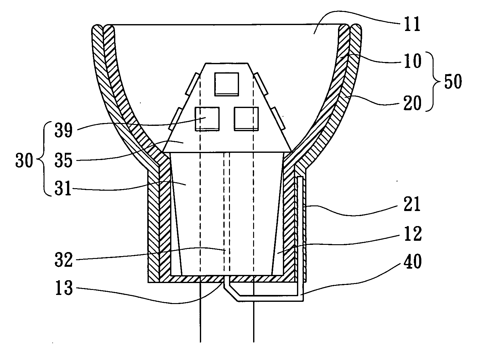
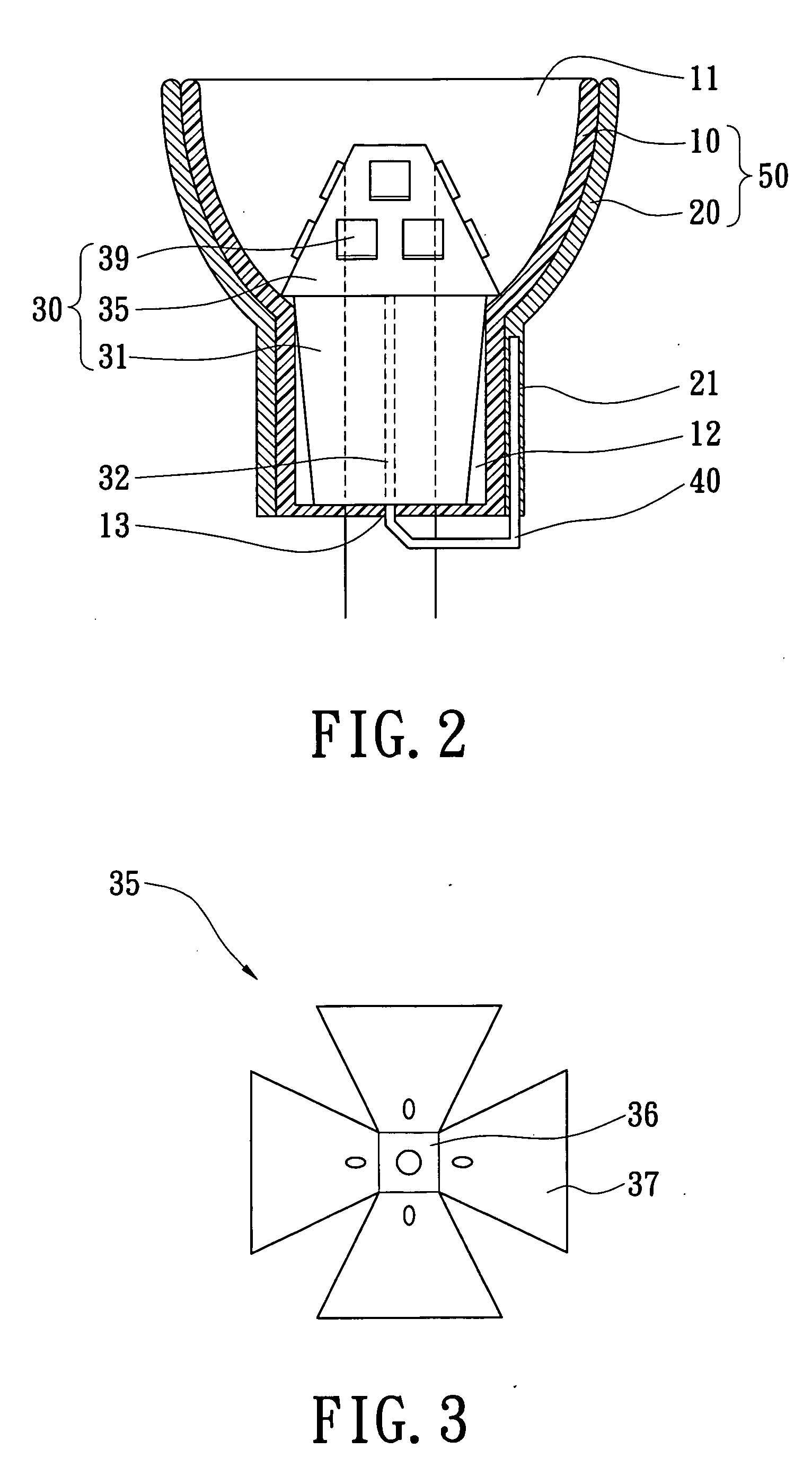
[0017] Referring now to FIGS. 2 to 5, the present invention provides an LED chip lamp apparatus comprising a heat sink with reflector 50, an LED lamp module 30 and a heat pipe 40. The LED lamp module 30 is assembled inside the reflector. An end of the heat pipe 40 connects to the LED lamp module 30 and the other end of the heat pipe 40 connects to the heat sink 50 so that the LED lamp module 30 generates heat transmitted to the heat sink 50 by the heat pipe 40 to disperse heat to increase the lifetime and the light emitting efficiency.

[0018] Referring now to FIG. 2, the heat sink with reflector 50 comprises a heat conductor 20 and a reflector housing 10. The heat conductor 20 surrounds the reflector housing 10, and the one end of the heat pipe 20 connects to the heat conductor 20. The reflector housing 10 has two ends. One end forms an o...


PUM


Abstract

An LED chap lamp apparatus has a heat sink with a reflector, an LED lamp module and a heat pipe. The LED lamp module is assembled on an inside of the reflector for reflecting light of the LED lamp module. The two ends of the heat pipe each connect to the LED lamp module and the heat sink to conduct and disperse the heat produced form the LED chips to increase the lifetime and the light-emitting efficiency of the LED chap lamp apparatus.

Description

BACKGROUND OF THE INVENTION [0001] 1. Field of the Invention [0002] The present invention relates to an LED chip lamp apparatus for transmitting and dispersing heat generated from the LED chips. [0003] 2. Description of the Related Art [0004] Reference is made to FIG. 1. A conventional LED chip lamp apparatus includes a retaining body 10a, a coupling member 20a, a reflector housing 30a, an electrical conduction barrel 40a, a transparent cover 50a and a plurality of LED chips 60a. The retaining body 10a has a concavity portion 11a with the reflector housing 30a positioned therein. Both the retaining body 20a and the reflector housing 30a respectively have a first through hole 12a, and the two first through holes 12a are communicated to each other. The coupling member 20a has two ends; each extends through the first through hole 12a of the retaining body 20a and the reflector housing 30a to engage the first through hole 12a edge on the retaining body 20a and the reflector housing 30a....

Claims


Application Information

Patent Timeline
Patent Type & Authority Applications(United States)
IPC IPC(8): F21S2/00F21K99/00F21V7/04
CPCF21K9/00F21Y2101/02F21Y2111/007F21V29/83F21V29/505F21V29/74F21V29/006F21Y2107/40F21Y2115/10
Inventor WANG, BILYCHUANG, JONNIEKO, CHING HUNG
Owner HARVATEK CORPORATION
Why Eureka
Try Eureka