

Modular array arrangements
- Summary
- Abstract
- Description
- Claims
- Application Information
AI Technical Summary
Benefits of technology
Problems solved by technology
Method used
Image

Examples
Embodiment Construction
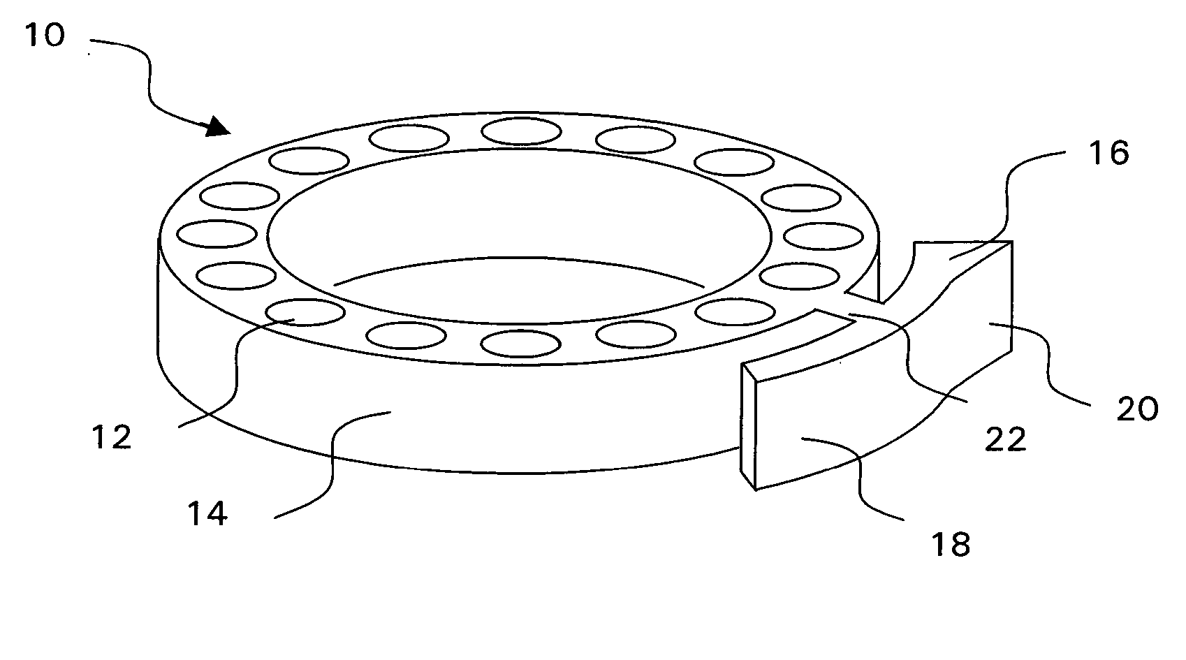
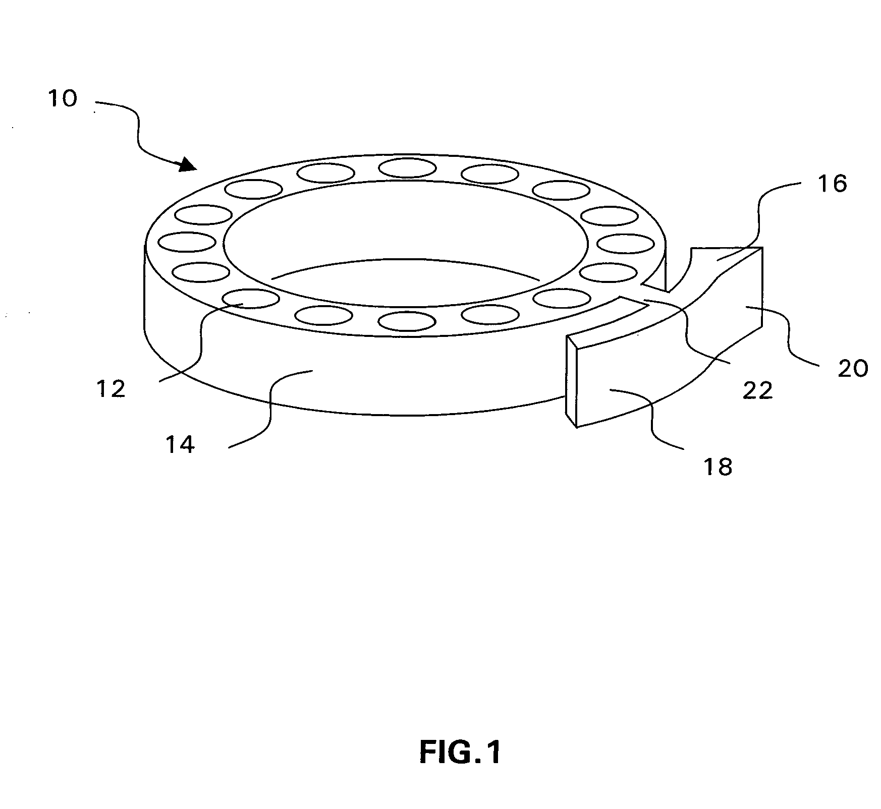
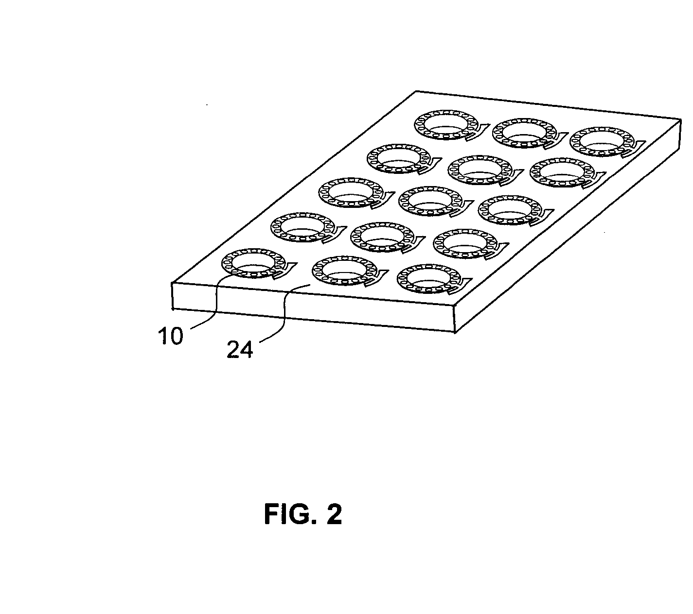
[0012] The term “array” as used in the present application may be understood as a collection of one or more section(s) arranged in a spatially defined and physically addressable manner, said section(s) being defined for receiving a sample and being provided with and / or adapted for receiving operational means.
[0013] The term “insert” as used in the present application shall designate any form that may be applied to a carrier, such as a container, a plate, a dish or a ring.
[0014] The term “sample” as used in the present application comprises any compound or mixture of compounds, in solid, liquid or gaseous form, which are of interest e.g. for performing an assay on the insert, as well as e.g. biological material when for example strains of interest have to be cultivated or examined.
[0015] The term “probe” as used in the present application shall designate any surface-immobilized molecule(s) that may bind to a particular target.
[0016] The term “target” as used in the present applic...
PUM
| Property | Measurement | Unit |
|---|---|---|
| Structure | aaaaa | aaaaa |
Abstract
Description
Claims
Application Information