J-channel and siding boards attachment structure

a technology of j-channel and attachment structure, which is applied in the direction of building components, construction, building construction, etc., can solve the problems of high total cost of construction members, high cost of j-channel, and structure not necessarily advantageous, and achieve the effect of high production cost and easy construction

Inactive Publication Date: 2005-11-17
NICHIHA CORP
View PDF5 Cites 1 Cited by
  • Summary
  • Abstract
  • Description
  • Claims
  • Application Information

AI Technical Summary

Benefits of technology

[0010] The present invention has been made in view of overcoming the aforementioned problems that may be high production cost, lack of a constructing property and restriction of arranging location. Therefore, an object of the present invention is to provide a J-Channel which is inexpensive because of its easy construction and is possible to use in several board sidings to be employed.

Problems solved by technology

Consequently, it causes the high total cost of members for construction.
But the J-Channel consists of two joint-parts, and its joint-mechanism is complicated, so it causes the high cost for the J-Channel.
Further, since two members are used, the structure is not necessarily advantageous in the light of a constructing property.

Method used


Image

  • J-channel and siding boards attachment structure
  • J-channel and siding boards attachment structure
  • J-channel and siding boards attachment structure

Examples


embodiment 1

[0053] A description is given of a J-Channel and a siding boards attachment structure using the same in accordance with an embodiment of the present invention with reference to FIGS. 1 to 8.

[0054] A J-Channel 1 in accordance with the present embodiment is formed in approximately J-shaped cross section and configured to be arranged so as to cover an end portion 41 of a siding board 4 as shown in FIGS. 4 to 6.

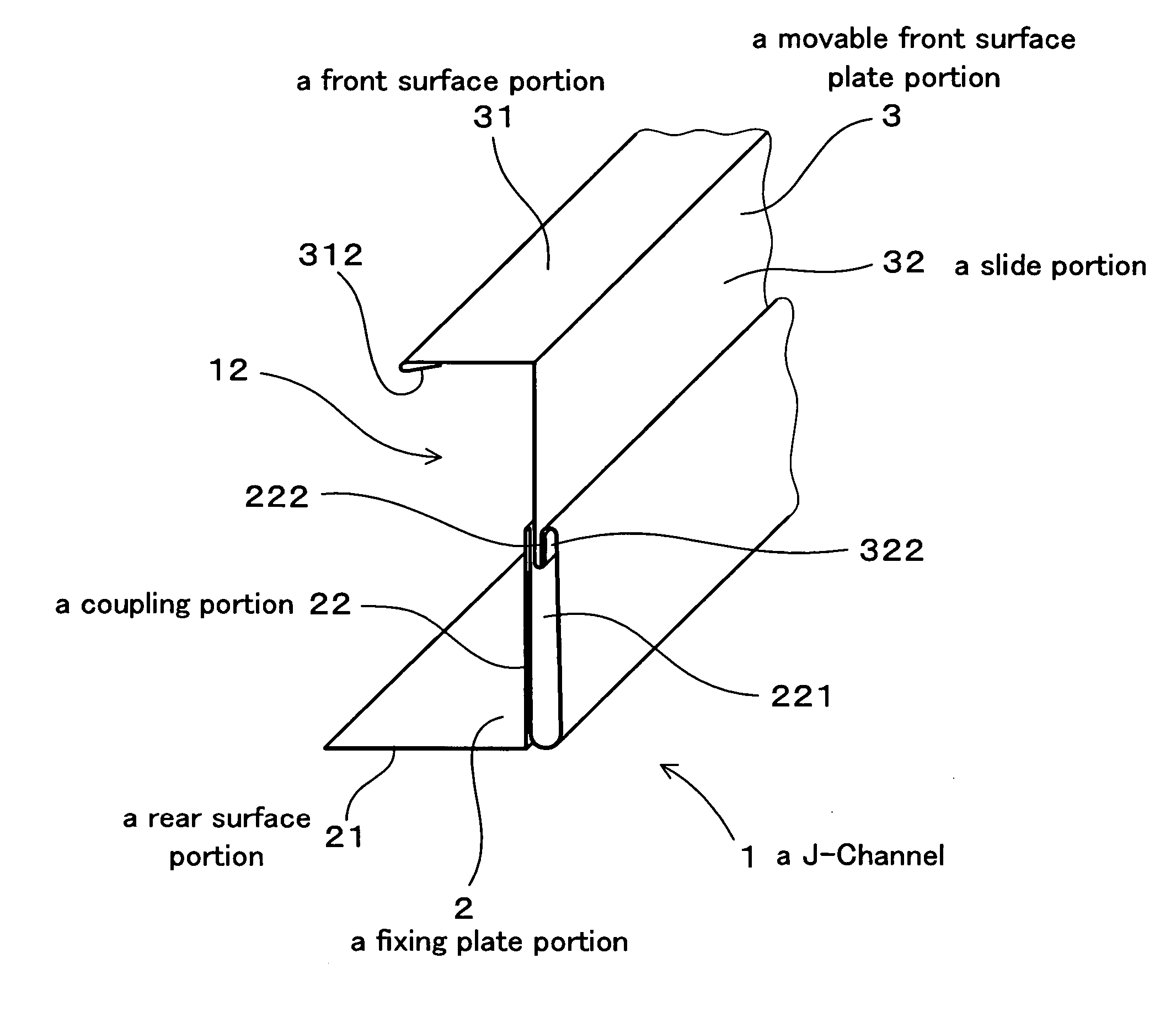
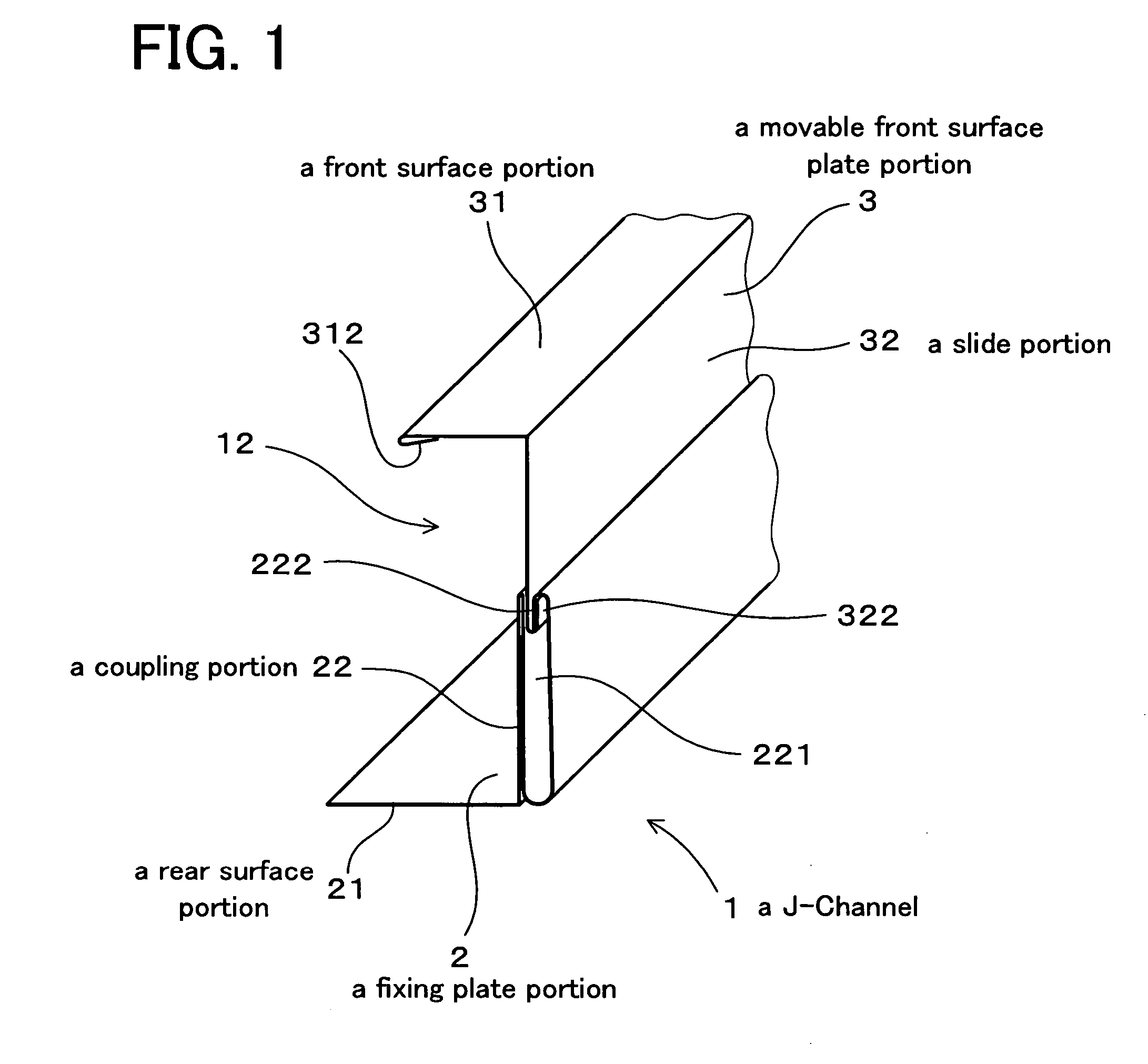
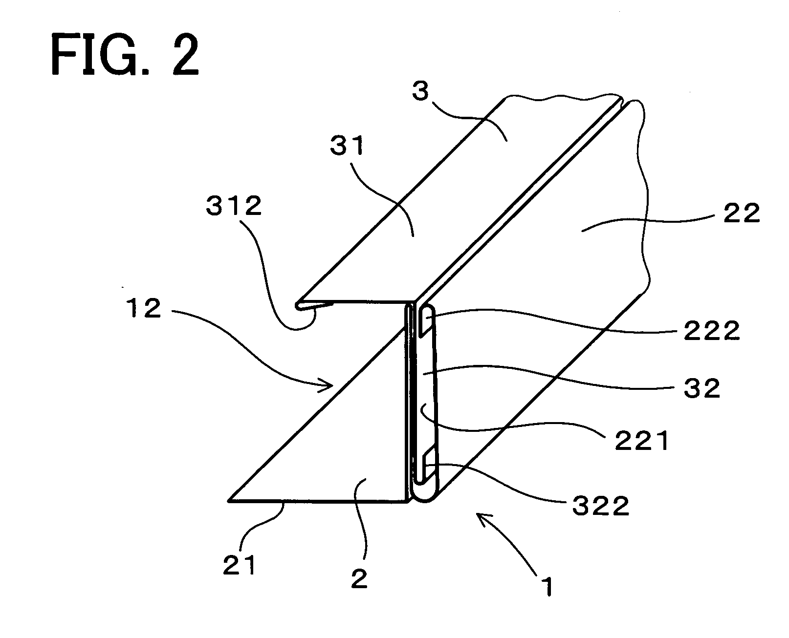
[0055] The J-Channel 1 is constituted by a fixing plate portion 2 configured to be fixed to an existing wall 51 (refer to FIGS. 4 and 5) being a backing of the siding board 4 and having an approximately L-shaped cross section, and a movable front surface plate portion 3 assembled in the fixing plate portion 2 so as to be slidable forward and backward and having an approximately L-shaped cross section, as shown in FIGS. 1 to 3.

[0056] The fixing plate portion 2 is constituted by a rear surface portion 21 configured to be arranged in a rear side of the siding board 4, and a coupl...

embodiment 2

[0085] The present embodiment corresponds to an example in which the J-Channel 1 is arranged in the end portion 41 of the siding board 4 arranged in the external corner portion of the building, as shown in FIG. 9.

[0086] There is a case that the siding board 4 is cut for adjusting the size and a cut surface is exposed, even in the external corner portion. The J-Channel 1 in accordance with the present invention is arranged so as to cover the end portion 41 having the cut surface.

[0087] The other structures are the same as the embodiment 1, and the same operation and effect as those of the embodiment 1 are provided.

embodiment 3

[0088] The present embodiment corresponds to an example in which the J-Channel 1 is arranged in a joint portion of the siding boards 4 having different thicknesses.

[0089] In the siding boards attachment structure 5 in accordance with the present embodiment, the siding board 4 having a larger thickness and the siding board 40 having a smaller thickness than the siding board 4 are arranged adjacently, and a joint filler 56 is placed therebetween. Further, a single hut joiner 561 is arranged in a rear side of the joint filler 56.

[0090] The siding board 4 having the larger thickness is fastened to the furring strip 521 by a fastening fitting 57, and the siding board 40 having the smaller thickness is fastened to the furring strip 521 by a nail 543.

[0091] Further, the J-Channel 1 is arranged so as to cover the end portion 41 of the siding board 4 having the larger thickness. Further, the rear surface portion 21 of the fixing plate portion 2 of the J-Channel 1 is arranged between the f...


PUM


Abstract

The invention provides an inexpensive J-Channel which is excellent in a constructing property and a general-purpose property, and a siding boards attachment structure using the same. The invention provides a J-Channel configured to be arranged so as to cover an end portion of a siding board. The J-Channel comprises a fixing plate portion configured to be fixed to a backing of the siding board, and a movable front surface plate portion assembled in the fixing plate portion so as to be slidable forward and backward. The fixing plate portion comprises a rear surface portion and a coupling portion. The movable front surface plate portion comprises a front surface portion and a slide portion. The coupling portion and the slide portion are engaged in a state in which they are slidable with each other.

Description

CROSS-REFERENCES TO RELATED APPLICATIONS [0001] The present application claims priority under 35 U.S.C. §119 to Japanese Patent Application No. 2004-146418, filed May 17, 2004, entitled “J-CHANNEL AND SIDING BOARDS ATTACHMENT STRUCTURE”. The contents of this application are incorporated herein by reference in their entirety. BACKGROUND OF THE INVENTION [0002] 1. Field of the Invention [0003] The present invention relates to a J-Channel employed for a board siding so as to cover an end portion of a siding board. The present invention also relates to a siding boards attachment structure using the J-Channel. [0004] 2. Discussion of the Background [0005] In related arts, conventionally, a J-Channel is used so as to cover an end portion of a siding board, for example, a top portion of the siding board arranged in a portion under eaves of the building. The J-Channel is formed in approximately J-shaped cross section having a front surface portion, a rear surface portion and a top surface p...

Claims


Application Information

Patent Timeline
Patent Type & Authority Applications(United States)
IPC IPC(8): E04F19/02E04F19/00E06B3/26
CPCE04F19/02
Inventor YOSHIDA, AKIHIRO
Owner NICHIHA CORP
Why Eureka
Try Eureka