Adjustment structure of seat belt device in vehicle

a seat belt and adjustment structure technology, applied in the direction of vehicle safety belts, belt anchoring devices, vehicle components, etc., can solve the problem that the seat belt device cannot exhibit sufficient occupant restraining performance, and achieve the effect of occupant restraining performance of the seat bel

Inactive Publication Date: 2005-11-17
HONDA MOTOR CO LTD
View PDF8 Cites 31 Cited by
  • Summary
  • Abstract
  • Description
  • Claims
  • Application Information

AI Technical Summary

Benefits of technology

[0007] The present invention is made in view of the above-described circumstances, and has an object to ensure an occupant restraining performance of a seat belt by preventing a lock releasing button of a slide plate of a seat belt device from being pressed by a deploying airbag.

Problems solved by technology

This prevents the situation in which the slip joint is moved downward together with the slide plate to loosen the webbing and a seat belt device cannot sufficiently exhibit an occupant restraining performance.

Method used


Image

  • Adjustment structure of seat belt device in vehicle
  • Adjustment structure of seat belt device in vehicle
  • Adjustment structure of seat belt device in vehicle

Examples


Embodiment Construction

[0033] An embodiment of the present invention will be described below based on the attached drawings.

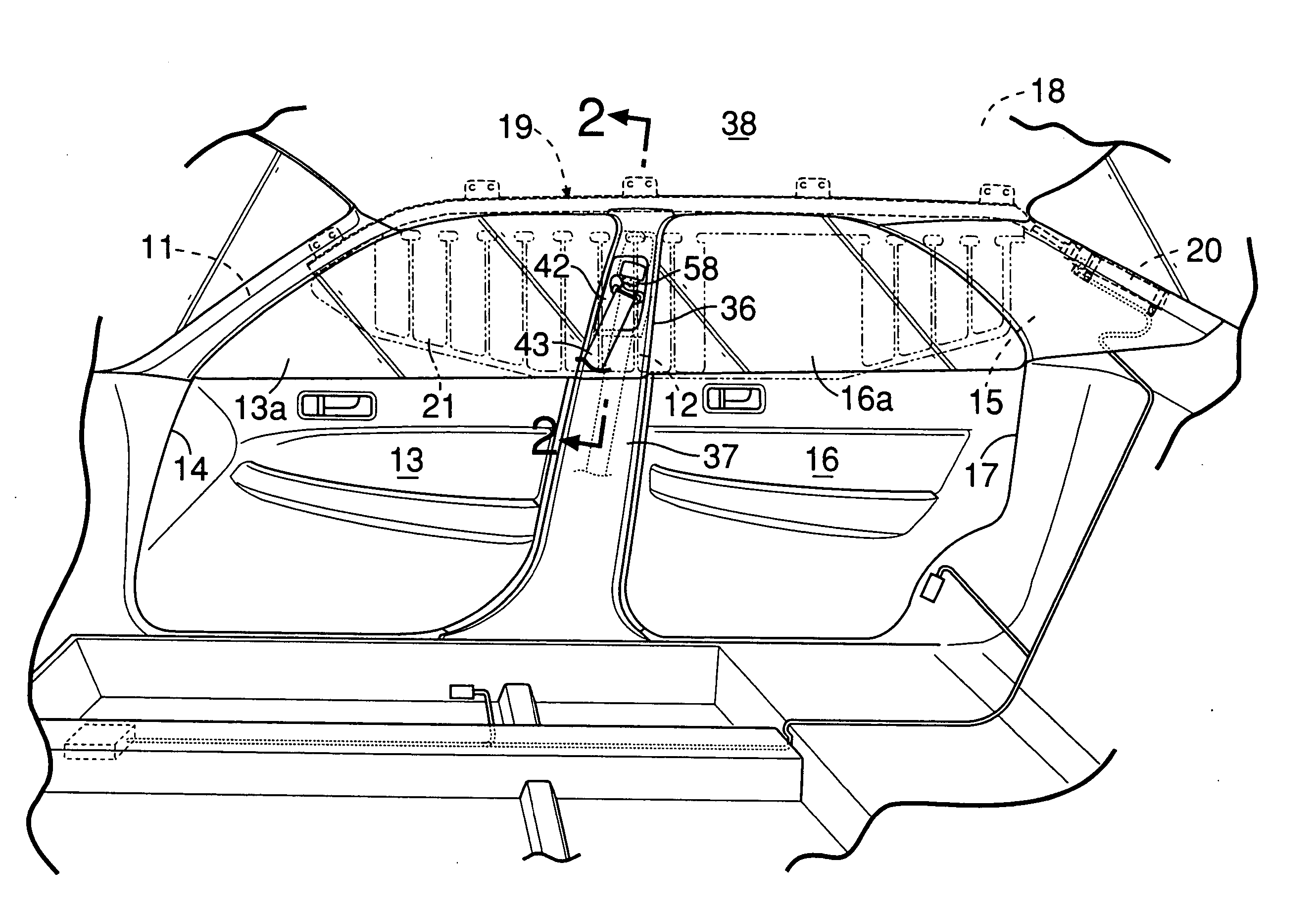
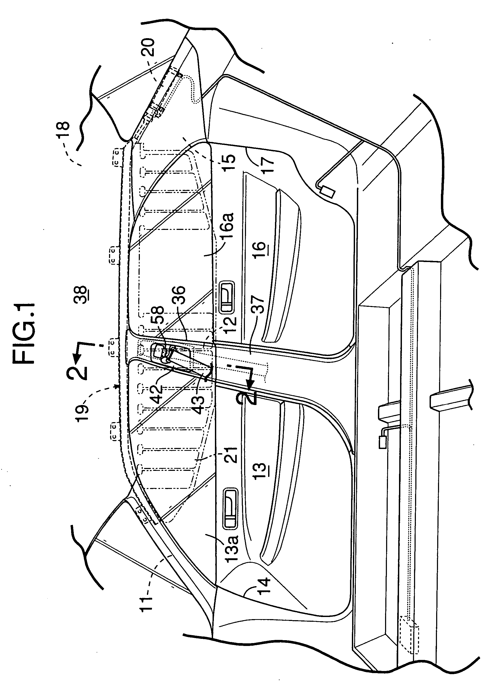
[0034] As shown in FIG. 1, on a side surface of a vehicle body of a vehicle, a door opening 14 in which a front door 13 is mounted is formed between a front pillar 11 and a center pillar 12, and a door opening 17 in which a rear door 16 is mounted is formed between the center pillar 12 and a rear pillar 15. An airbag module 19 is provided along a side edge of a roof 18 which extends from an upper end of the front pillar 11 to an upper end of the rear pillar 15. When acceleration of a predetermined value or higher is detected at a time of collision on the side surface of the vehicle or at a time of rolling over, an airbag 21 accommodated in the airbag module 19 is inflated by a high pressure gas which is supplied from an inflator 20 disposed inside the rear pillar 15, and deploys downward into a curtain shape from the side edge of the roof 18 so as to shield occupants seated on a fro...


PUM


Abstract

A lock releasing button is provided at a slide plate including a slip joint for slidably supporting a webbing for restraining an occupant to a seat. Locking of the slide plate to a center pillar is arranged to be released when the lock releasing button is pressed upward from below. Therefore, when an airbag presses to open a connecting portion between a roof lining and a pillar garnish and deploys downward at a time of collision of a vehicle, the lock releasing button is prevented from releasing the locking by being pressed by the airbag deploying downward. This prevents the situation in which the slip joint is moved downward together with the slide plate to loosen the webbing and thus a seat belt device cannot sufficiently exhibit an occupant restraining performance.

Description

BACKGROUND OF THE INVENTION [0001] 1. Field of the Invention [0002] The present invention relates to a structure for adjusting a vertical position of a slip joint in a vehicle including an airbag device for deploying an airbag downward along an inner surface of a side portion of a vehicle compartment from a side edge of a roof, and a seat belt device in which a middle portion of a webbing is slidably guided by a slip joint provided at a pillar. [0003] 2. Description of the Related Art [0004] Japanese Patent No. 3460636 discloses a seat belt device wherein a slide plate 52, to which a slip joint 51 for slidably guiding a webbing for restraining an occupant to a seat is fixed via an adjustable anchor 53, is supported along an inner surface of a center pillar garnish 22 to be movable up and down; projecting portions 22a and 52a triangular in section are formed at the center pillar garnish 22 or the slide plate 52 above the slip joint 51; and an airbag 31 which is deploying is guided wi...

Claims


Application Information

Patent Timeline
Patent Type & Authority Applications(United States)
IPC IPC(8): B60R21/20B60R21/213B60R22/00B60R22/18B60R22/20B60R22/24
CPCB60R22/203B60R21/213
Inventor UNO, KOJIIKEDA, KOJIKAJIWARA, HIDEKINISHIZAKA, MITSUHIROSEKIGUCHI, NOBUMOTO
Owner HONDA MOTOR CO LTD
Why Eureka
Try Eureka