Plasma display apparatus and driving method thereof

Inactive Publication Date: 2006-05-25
LG ELECTRONICS INC
View PDF4 Cites 5 Cited by
  • Summary
  • Abstract
  • Description
  • Claims
  • Application Information

AI Technical Summary

Benefits of technology

[0058] The present invention can reduce generation of noise and stabilize a discharge of a PDP under high tempera

Problems solved by technology

More particularly, in the case of a specific pattern in which a logic value of image data is repeated between 0 and 1, the amount of the displacement current flowing through the data driver IC is excessively increased.
Therefore, there is a problem in electrical damage such as a burnt data driver IC.
Therefore, problems arise because a dark room contrast value is lowered and the contrast ratio is lowered accordingly.
Furthermore, in the conventional plasma display apparatus, in the case where negative wall charges are excessively accumulated on the scan electrodes Y since wall charges are not smoothly erased in the erase period (EP) of the (n−1)th sub-field (SFn−1), a dark discharge is not generated in the set-up period (SU) of the nth sub-field (SFn).
If the dark discharge is not generated in the set-up period (SU), a condition within the discharge cells immediately after the reset period does not become an optimal address condition.
This results in an abnormal discharge or erroneous discharge.
Therefore, initialization is not uniform over the entire cells.
In other words, if a strong erase discharge is generated in the erase period prior to the reset period, an erroneous discharge can be generated.
Consequently, if an erase discharge is not generated or is very weakly generated in the erase period prior to the reset peri

Method used


Image

  • Plasma display apparatus and driving method thereof
  • Plasma display apparatus and driving method thereof
  • Plasma display apparatus and driving method thereof

Examples


first embodiment

[0105]FIGS. 9a and 9b are views illustrating a driving method of a plasma display apparatus according to the present invention.

[0106] Referring first to FIG. 9a, in the method of driving the plasma display apparatus according to a first embodiment of the present invention, the plasma display apparatus is driven with a driving waveform being divided into a reset period, an address period and a sustain period in one frame, as described above.

[0107] In a set-up period of the reset period, a ramp-up waveform (Ramp-up) is applied to scan electrodes Y. The ramp-up waveform generates a weak dark discharge within discharge cells of the entire screen. The ramp-up discharge also causes positive wall charges to be accumulated on data electrodes X and sustain electrodes Z, and negative wall charges to be accumulated on the scan electrodes Y.

[0108] In a set-down period of the reset period, after the ramp-up waveform is applied to the scan electrodes Y, a ramp-down waveform (Ramp-down), which f...

second embodiment

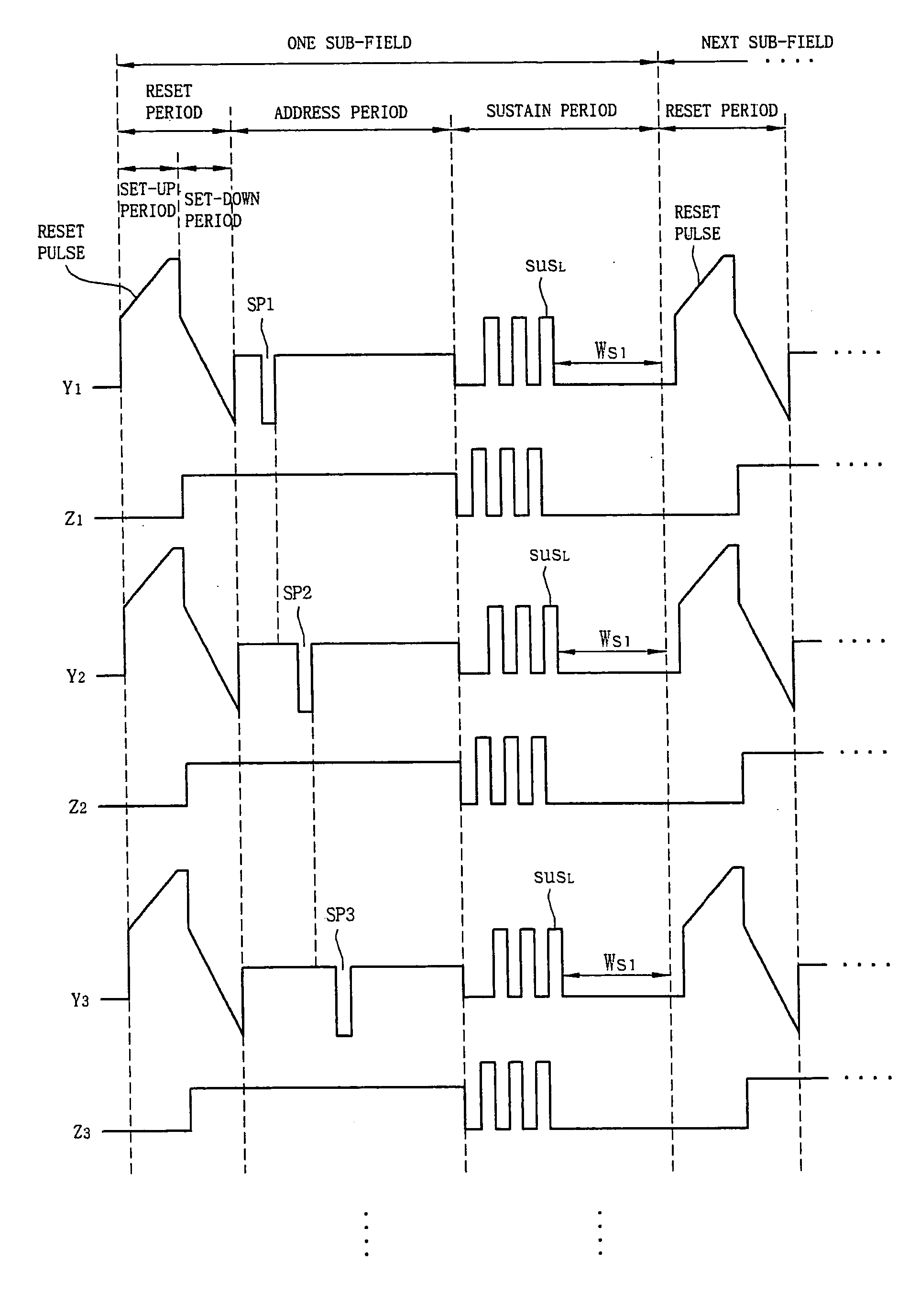
[0304]FIG. 27 is a view illustrating a method of controlling a difference between an application time of a last sustain pulse and an application time of a reset pulse applied in a reset period of a next sub-field according to the present invention.

[0305] Referring to FIG. 27, (a) of FIG. 27 shows the relation between a last sustain pulse (SUSL) applied in a sustain period of any one of sub-fields and a reset pulse applied in a reset period of a next sub-field. FIG. 27 shows a case where the last sustain pulse (SUSL) is applied to the scan electrodes Y. It is, however, to be noted that the last sustain pulse (SUSL) can be applied to the sustain electrodes Z.

[0306] (b) of FIG. 27 shows a difference (Ws2) between application times in the remaining sustain pulses other than the last sustain pulse (SUSL).

[0307] Referring to (a), a time lag of Ws1 is placed between then application time of the last sustain pulse (SUSL) and the application time of a reset pulse applied in a reset period ...


PUM


Abstract

The present invention relates to a plasma display apparatus, and more particularly, to a plasma display apparatus and driving method thereof, in which scan electrodes are scanned according to one of a plurality of scan types and a last sustain pulse of sustain pulses applied to scan electrodes or sustain electrodes is controlled. The plasma display apparatus of the present invention comprises a plasma display panel comprising a plurality of scan electrodes, a plurality of sustain electrodes, and a plurality of data electrodes crossing the plurality of scan electrodes and the sustain electrodes, and a controller for scanning the scan electrodes using one of a plurality of scan types in which the order of scanning the plurality of scan electrodes is different in an address period, applies a data pulse to the data electrodes corresponding to one scan type, and controls a difference between an application time point of a last sustain pulse of sustain pulses, which are applied to the scan electrodes or the sustain electrode in a sustain period subsequent to the address period, and a application time point of a reset pulse, which is applied to the scan electrodes in a reset period of a next sub-field, to be greater than a difference between application time points of the two sustain pulses, in at least one of sub-fields of a frame.

Description

CROSS-REFERENCES TO RELATED APPLICATIONS [0001] This Nonprovisional application claims priority under 35 U.S.C. §119(a) on Patent Application No. 10-2004-0095455 filed in Republic of Korea on Nov. 19, 2004, Patent Application No. 10-2005-0090172 filed in Republic of Korea on Sep. 27, 2005, the entire contents of which are hereby incorporated by reference. BACKGROUND OF THE INVENTION [0002] 1. Field of the Invention [0003] The present invention relates to a plasma display apparatus, and more particularly, to a plasma display apparatus and driving method thereof, in which scan electrodes are scanned according to one of a plurality of scan types and a last sustain pulse of sustain pulses applied to scan electrodes or sustain electrodes is controlled. [0004] 2. Background of the Related Art [0005] In general, a plasma display panel comprises a front panel and a rear panel. Barrier ribs formed between the front panel and the rear panel form one cell. Each cell is filled with a primary di...

Claims


Application Information

Patent Timeline
IPC IPC(8): G09G3/28G09G3/20G09G3/288G09G3/291G09G3/292G09G3/294G09G3/296G09G3/298
CPCG09G3/292G09G3/294G09G2310/0267G09G2320/041G09G2330/021
Inventor JUNG, YUNKWONKANG, SEONGHOYOON, SANGJINSIM, SOOSEOK
Owner LG ELECTRONICS INC
Why Eureka
Try Eureka